Rotor bearing for electrical machine

一种转子、发电机的技术,应用在机电装置、风力电机组合、旋转运动的轴承等方向,能够解决无法有利地使用风力发电设备等问题

Active Publication Date: 2014-02-05
IMO HOLDING GMBH
View PDF7 Cites 0 Cited by
  • Summary
  • Abstract
  • Description
  • Claims
  • Application Information

AI Technical Summary

Problems solved by technology

Such generators cannot be used advantageously in wind power plants since there is only little space available, especially in wind power plants

Method used


Image

  • Rotor bearing for electrical machine
  • Rotor bearing for electrical machine
  • Rotor bearing for electrical machine

Examples


Embodiment Construction

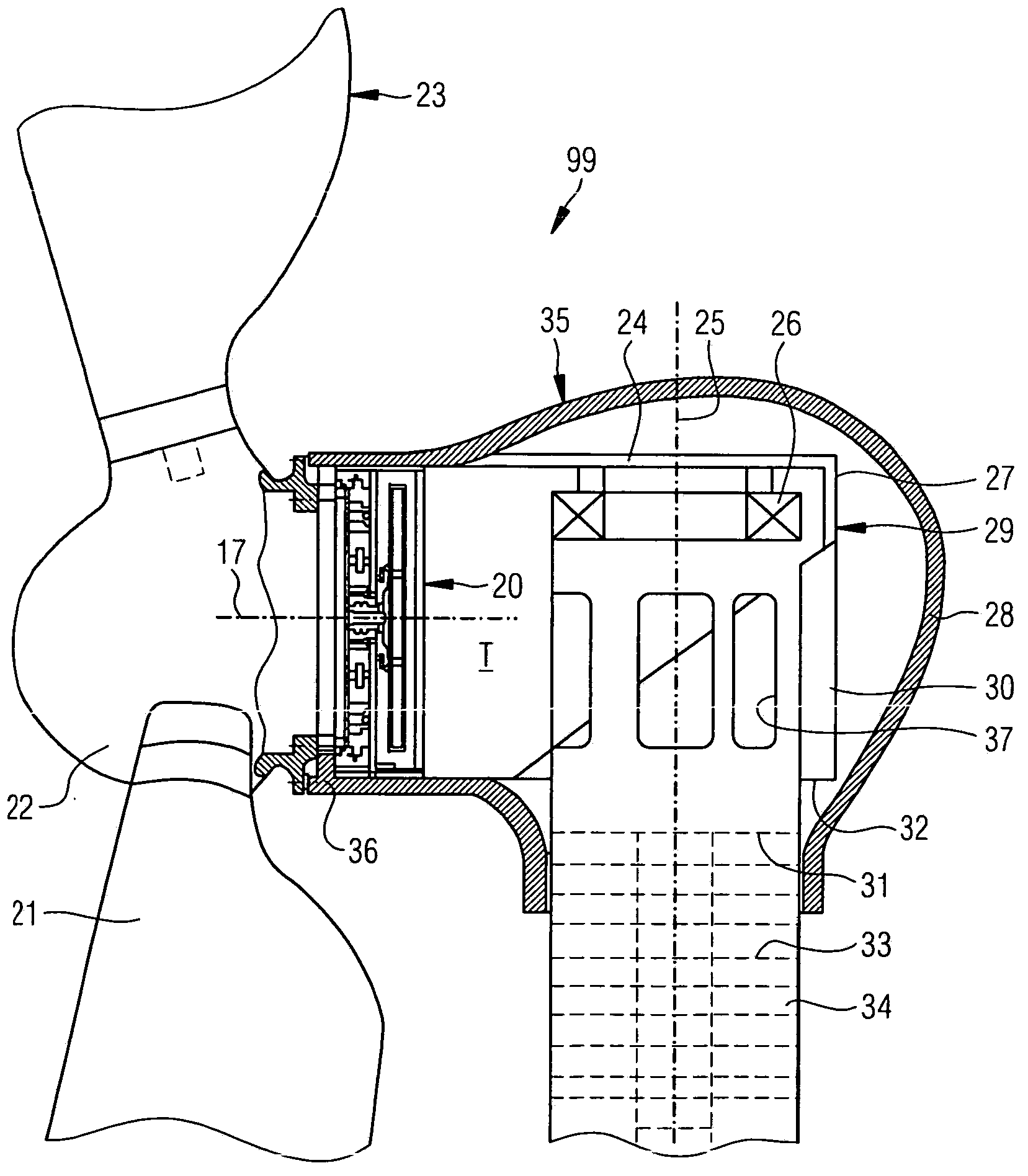
[0042] exist figure 1 The structure of a nacelle 35 of a wind power plant 99 which is suitable for using a disk rotor generator according to the invention is depicted in .

[0043] Here the upper end of the tower 34 with a circular cross section is seen, the nacelle 35 being pivotably fitted about the vertical tower axis 25 via the machine room bearing 26 mounted in the horizontal position for orientation adjustment on the upper end. If one ring of the machine room bearing 26 is fixed on the upper side of the tower 34 , then the other ring can be pivoted about the tower axis 25 by means of a drive not shown.

[0044] An upper plate or frame 24 of a load-bearing structure 29 pivotable about a tower axis 25 is supported on a pivotable ring of machine room bearings 26 . The carrier structure 29 forms, so to speak, the inner shell of the machine room 35 and is accessible by maintenance personnel via a lift, a ladder 33 or stairs in the tower 34 and via a lateral exit 37 in the w...


PUM


Abstract

The invention is directed firstly at a disc-rotor generator for generating electrical energy from the rotation energy of a power installation which is driven in rotation, preferably a continuous-flow power installation, in particular a wind power installation, having at least two stator components which are axially offset in relation to one another along an approximately horizontal rotation axis of the disc rotor, and having at least one ring- or disc-like rotor component of the disc rotor, which rotor component is mounted between said stator components so as to rotate about the rotation axis, having an input-end connection for a gear mechanism, preferably a step-up gear mechanism, in particular a planetary gear mechanism, wherein the output shaft of said gear mechanism, in particular the sun gear of said gear mechanism, which runs coaxially to the rotation axis of the disc rotor is coupled to at least one ring- or disc-like rotor component of the disc rotor, wherein the roller bearing which is associated with a ring- or disc-like rotor component of the disc rotor is in the form of an angular ball bearing or is formed with angular ball bearings, for example with a supporting angle of between 40° and 50° in relation to the rotation axis, preferably in the form of a two-row angular ball bearing, in particular as a two-row angular ball bearing in O-arrangement; and secondly at a wind power installation which is equipped with said disc-rotor generator.

Description

technical field [0001] The present invention relates to a rotor support for an electrical machine, in particular to a disc rotor generator for generating electrical energy from the rotational energy of a rotationally driven power plant, preferably a fluid flow power plant, in particular a wind power plant machine with at least two stator parts axially offset from each other along the substantially horizontal axis of rotation of the disk rotor and with at least one of the disk rotors arranged therebetween so that by means of a single rolling An annular or disk-shaped rotor part supported by the supporting device in rotation about an axis of rotation. The invention also relates to a wind power plant so equipped. Background technique [0002] Rotating plant and machine components are usually supported in the prior art by means of roller bearings. [0003] Laid-open document DE 10 2004 021 138 A1 describes, for example, an electric machine and its mounting, in which the fixed b...

Claims


Application Information

Patent Timeline
Patent Type & Authority Applications(China)
IPC IPC(8): F03D9/00H02K21/24H02K7/08H02K7/116H02K7/18
CPCH02K7/083H02K7/1838Y02E10/725H02K21/24F03D9/002H02K7/116F16C19/54F03D9/25F16C2380/26F16C2360/31Y02E10/72F03D80/70F03D15/10H02K7/09
Inventor 格奥尔格·霍夫曼斯特凡·萨德尔约翰尼斯·登纳莱因
Owner IMO HOLDING GMBH
Why Eureka
Try Eureka