Design improvements for flux switching machines

A magnetic flux, switching motor technology, used in electronically commutated motor control, synchronous motors for single-phase currents, magnetic circuits, etc.

Inactive Publication Date: 2014-02-05
TECHNELEC
View PDF8 Cites 7 Cited by
  • Summary
  • Abstract
  • Description
  • Claims
  • Application Information

AI Technical Summary

Problems solved by technology

In fact, the torque output from the three-phase flux switching machine excited by sinusoidal excitation can be smooth without large torque dips or reversals as described in PCT / GB2009 / 001921

Method used


Image

  • Design improvements for flux switching machines
  • Design improvements for flux switching machines
  • Design improvements for flux switching machines

Examples


Embodiment Construction

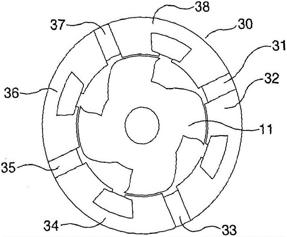
[0069] Image 6 The rotor is shown. Slotted models have been cut into rotor laminations. The slots 210 are shaped to reinforce the 4-pole pattern on the rotor. These slots introduce air between the steel segments and thus have high magnetic permeability. It is now more difficult for magnetic flux to permeate at right angles to the slot than permeate parallel to the slot. exist Image 6 , there are 4 sets of slots in each rotor tooth, and these slots are arranged in two pairs linked with corresponding pairs on adjacent rotor teeth. Such slots are proposed for synchronous reluctance motors in order to improve the ratio between direct and quadrature inductance.

[0070] Its use in flux switching motors has never been suggested because introducing air into the stator teeth would be seen as detrimental to inductance when the rotor teeth are in a position aligned with a set of stator teeth. To maintain mechanical rigidity, it is advantageous to leave some material 211 to bridge ...


PUM


Abstract

It is the object of this invention to provide a design for flux switching machines with a one or more armature windings which can deliver controlled torque, in either selected direction on start up, without the use of a mechanical position sensor. Rotor slotting 210 is introduced to create a path of low permeability across a rotor tooth with minimal impact on the normal torque producing flux paths, bridges 211 retaining the portions of the laminations together.. Asymmetry of stator slots e.g. 207, 208 is used to further create a stable rotor position when energised by predominantly field means or armature means. The method is suitable for starting permanent magnet flux switching motors. The invention discloses design features for such machines which improves the torque profile of the motor with angle. In three phase machines this delivers higher torque and lower ripple torque. In single phase flux switching machines the invention allows the rotor to be placed in a position where maximum torque can be delivered in either direction by selection of either positive or negative armature current.

Description

technical field [0001] The present invention relates to magnetic flux switching machines. More particularly, the present invention relates to, but is not limited to, improvements in rotor and stator design for improved torque versus angle variation. Background technique [0002] Brushless permanent magnet and reluctance motors are used in many applications because they do not require the use of commutators or brushes to supply power to the rotor of the motor. Since these components are subject to a great deal of wear, it is highly desirable to avoid their use. The rotor of a flux switching machine has lobed teeth with no windings or permanent magnets. These rotors are therefore simple to manufacture and very robust. They are suitable for a variety of applications including very high speed electrical machines. [0003] Figure 1 shows a flux switching machine with 8 stator teeth and 4 rotor teeth as described in US Patent 6,788,020. The motor comprises field windings in s...

Claims


Application Information

Patent Timeline
Patent Type & Authority Applications(China)
IPC IPC(8): H02P6/00H02P25/08H02K19/06
CPCH02K19/06H02P6/008H02P25/08H02K1/246H02P6/26H02K19/103H02K21/38H02P6/10H02P6/30H02P25/089H02K1/22H02K11/30
Inventor 查尔斯·波洛克海伦·波洛克
Owner TECHNELEC
Why Eureka
Try Eureka