
Waste gas purification tower

A purification tower and exhaust gas technology, applied in chemical instruments and methods, separation of dispersed particles, use of liquid separation agent, etc., can solve the problems of insignificant effect, reduce the effective space between exhaust gas and foam, prolong the contact time between exhaust gas and foam, and achieve The overall structure is simple, the maintenance cost is reduced, and the purification rate is improved

Active Publication Date: 2014-02-12
SHISHI XINGHUO ALUMINUM PROD CO LTD
View PDF9 Cites 2 Cited by
  • Summary
  • Abstract
  • Description
  • Claims
  • Application Information

AI Technical Summary

Problems solved by technology

However, the effect of exhaust gas purification treatment is not good. One of the main reasons is that the exhaust gas is sent from the bottom of the tower under high pressure, and the exhaust gas rises directly and rapidly along the wind flow. In addition, the foam liquid cannot achieve a full tank, resulting in the contact time between the exhaust gas and the foam. Extremely short, most of the time the exhaust gas is sent to the top of the foam layer and discharged before it fully contacts with the foam
At present, a solution is to use two sets of foam adsorption devices. The gas outlet of the first set of foam scrubbers is connected to the gas input port of the second set of foam scrubbers. Although it can improve a certain exhaust gas purification rate, the effect is not good. significantly
At present, another solution is to further design the structure inside the tower. For example, in the patent application 201310118282.0, the foam layer (also the sieve plate mechanism) is provided with multiple layers, and a baffle is also provided under each layer. In practical application, The complex structural design not only reduces the effective space for the contact between the exhaust gas and the foam, not only does not prolong the contact time between the exhaust gas and the foam, but also causes a certain blockage to the circulation of the exhaust gas and affects the normal operation of the device. In addition, it also brings load to the cleaning and maintenance of the equipment burden

Method used


Image

  • Waste gas purification tower
  • Waste gas purification tower
  • Waste gas purification tower

Examples


Embodiment Construction

[0060] The present case will be described in further detail below in conjunction with the accompanying drawings and specific embodiments.

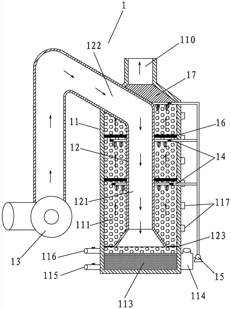
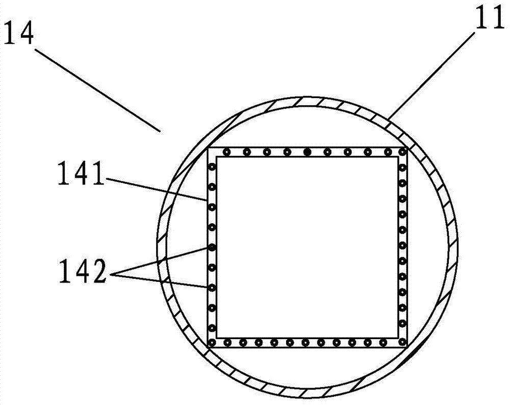
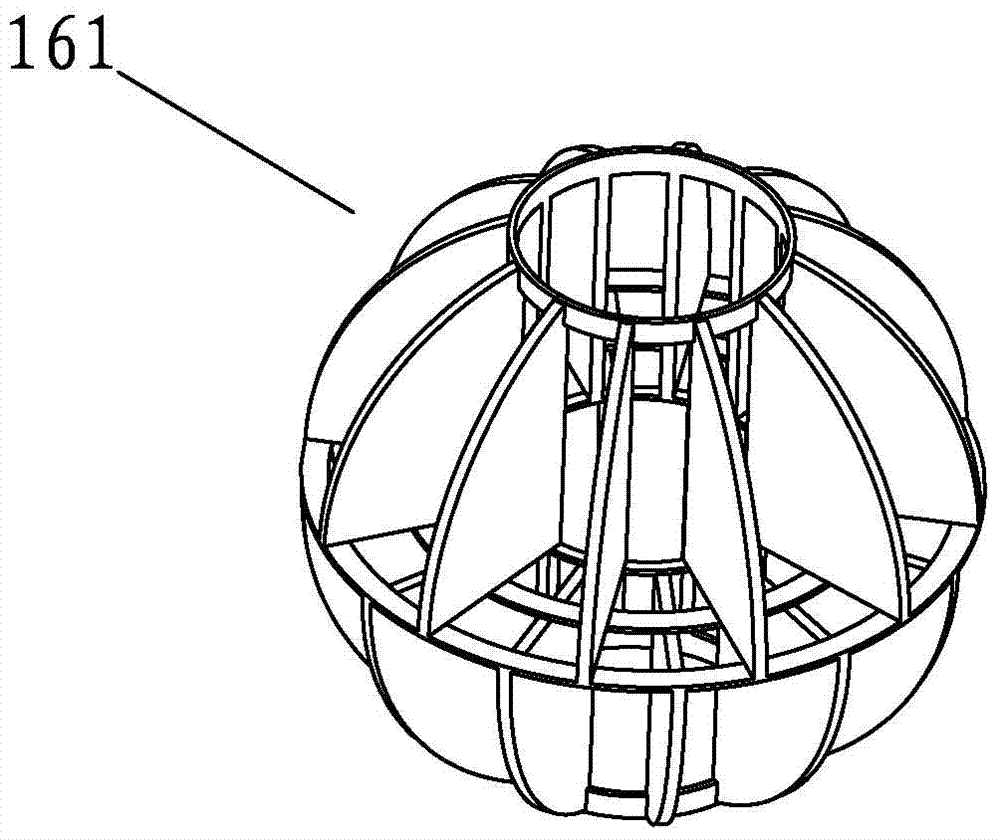
[0061] This case involves a waste gas purification tower, the first embodiment is as Figure 1-3 Shown is the first tower 1 , including the first tower body 11 , and the top of the first tower body 11 is provided with a first exhaust port 110 . A first inner tower tube 12 is sheathed in the first tower body 11 . The bottom of the first inner tower tube 12 is close to the bottom of the first tower body 11, and the inside and outside of the first inner tower tube 12 respectively form a first inner air chamber 121 and a first outer air chamber 111, and the first inner air chamber 121 and the first outer air chamber 111 The respective tops of the outer air chambers 111 are sealed and the respective bottoms are connected. A first air inlet 122 is opened on the side wall near the top of the first tower body 11 , and the first air inlet 122 com...


PUM


Abstract

The invention discloses a waste gas purification tower. The waste gas purification tower comprises a first tower body, wherein the top of the first tower body is provided with a first exhaust port; a first inner tower tube is sleeved inside the first tower body; the bottom of the first inner tower tube is close to the bottom of the first tower body; a first inner air chamber and a first outer air chamber are respectively arranged inside and outside the first inner tower tube; a first air inlet communicated with the first inner air chamber is formed in the side wall, close to the top end, of the first tower body; foam spray heads are distributed inside the first outer air chamber. The waste gas purification tower has the advantages of being simple in structure, high in purification rate, low in cost, free of cleaning and maintenance and the like, and can be widely applied to providing an excellent way for promoting the quality of social environment in industry, commercial business and life.

Description

technical field [0001] The invention relates to waste gas treatment technology, in particular to a waste gas purification tower. Background technique [0002] At present, exhaust gas treatment is widely used in various industrial places. There are many existing exhaust gas treatment methods, such as activated carbon adsorption, biological filter, plasma, catalytic oxidation, etc., all of which have a certain effect on exhaust gas purification. However, the treatment and purification effect is not good, and most of them still have problems such as complex equipment, high treatment cost, low purification rate, and high maintenance cost. [0003] Regarding the adsorption method, some people currently use foam adsorption to treat exhaust gas. For example, see the patent application (application number 201310118282.0) for a foam scrubber, which uses foam to treat exhaust gas. The specific treatment method is that a foam layer ( Specifically, the sieve plate mechanism), the waste...

Claims


Application Information

Patent Timeline
Patent Type & Authority Applications(China)
IPC IPC(8): B01D47/00B01D47/06B01D47/04B01D53/18
Inventor 陈兴星
Owner SHISHI XINGHUO ALUMINUM PROD CO LTD
Learn More