Stirrer

A technology for mixers and mixing boxes, applied in cement mixing devices, clay preparation devices, chemical instruments and methods, etc., can solve the problems of shortening the service life of mixer shafts, difficulty in replacing mixing blade blades, and easy bending and deformation of mixer shafts. The effect of making bricks, ensuring the degree of maturity of the mixing material, and improving the safety of use

Active Publication Date: 2014-02-12
LESHAN TAIGANG SUNKOS MACHINERY MFG
View PDF7 Cites 0 Cited by
  • Summary
  • Abstract
  • Description
  • Claims
  • Application Information

AI Technical Summary

Problems solved by technology

[0012] In the double-shaft mixer disclosed in this patent document, the mixing knife is directly sleeved on the stirring shaft, and one end of the stirring shaft is directly connected to the output shaft of the reducer. The connection method is connected by two cross coupling heads, one of which is Assembled on the stirring shaft, and the other cross coupling head is assembled on the low-speed shaft of the reducer. The span of the mixer shaft is too large. The degree of maturation of the mixing material is not high, and the brick-making effect is poor; the structure of the mixing knife blade directly passing through the mixer shaft will affect the stiffness of the shaft and shorten the service life of the mixer shaft; at the same time, this design structure will also make the mixing knife blade replaceable Difficult to increase the user's replacement cost of wearing parts during equipment use

Method used


Image

  • Stirrer
  • Stirrer

Examples


Embodiment 1

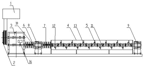
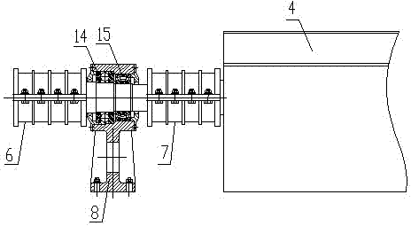
[0034] A mixer, including a motor 1, a clutch 2, a speed reducer 3, a mixing box 4, a stirring shaft, and a mixing knife blade 5, the motor 1 is connected to the speed reducer 3 through the clutch 2, the stirring shaft is driven by the motor 1, and a first clamping case is also included Coupling 6, the second clamshell coupling 7, front joint two bearing blocks 8, rear joint two bearing blocks 9, the stirring shaft is composed of the stirring short shaft 10 outside the stirring box 4 and the stirring shaft 10 inside the stirring box 4 Stirring long shaft 11 is formed, and one end of said stirring short shaft 10 is connected with the low-speed shaft of reducer 3 through the first shell coupling 6, and the other end is connected with the bearing inner hole of the second bearing seat 8 of the front coupling. One end of the shaft 11 is connected with the inner hole of the bearing of the second bearing seat 8 of the front coupling through the second shell coupling 7, and the other e...

Embodiment 2

[0037]A mixer, including a motor 1, a clutch 2, a speed reducer 3, a mixing box 4, a stirring shaft, and a mixing knife blade 5, the motor 1 is connected to the speed reducer 3 through the clutch 2, the stirring shaft is driven by the motor 1, and a first clamping case is also included Coupling 6, the second clamshell coupling 7, front joint two bearing blocks 8, rear joint two bearing blocks 9, the stirring shaft is composed of the stirring short shaft 10 outside the stirring box 4 and the stirring shaft 10 inside the stirring box 4 Stirring long shaft 11 is formed, and one end of said stirring short shaft 10 is connected with the low-speed shaft of reducer 3 through the first shell coupling 6, and the other end is connected with the bearing inner hole of the second bearing seat 8 of the front coupling. One end of the shaft 11 is connected with the inner hole of the bearing of the second bearing seat 8 of the front coupling through the second shell coupling 7, and the other en...

Embodiment 3

[0041] A mixer, including a motor 1, a clutch 2, a speed reducer 3, a mixing box 4, a stirring shaft, and a mixing knife blade 5, the motor 1 is connected to the speed reducer 3 through the clutch 2, the stirring shaft is driven by the motor 1, and a first clamping case is also included Coupling 6, the second clamshell coupling 7, front joint two bearing blocks 8, rear joint two bearing blocks 9, the stirring shaft is composed of the stirring short shaft 10 outside the stirring box 4 and the stirring shaft 10 inside the stirring box 4 Stirring long shaft 11 is formed, and one end of said stirring short shaft 10 is connected with the low-speed shaft of reducer 3 through the first shell coupling 6, and the other end is connected with the bearing inner hole of the second bearing seat 8 of the front coupling. One end of the shaft 11 is connected with the inner hole of the bearing of the second bearing seat 8 of the front coupling through the second shell coupling 7, and the other e...


PUM


Abstract

The invention discloses a stirrer which comprises a motor, a clutch, a reducer, a stirring box, a stirring shaft, stirring knife blades, a first clamp coupling, a second clamp coupling, a front link double bearing pedestal and a rear link double bearing pedestal, wherein the stirring shaft consists of a stirring short shaft and a stirring long shaft; one end of the stirring short shaft is connected with a slow-speed shaft of the reducer by the first clamp coupling; the other end of the stirring short shaft is connected with a bearing bore of the front link double bearing pedestal; one end of the stirring long shaft is connected with the bearing bore of the front link double bearing pedestal by the second clamp coupling; the other end of the stirring long shaft is connected with a bearing bore of the rear link double bearing pedestal; the stirring long shaft is sleeved with a threaded protective sleeve; a stirring knife holder is welded on the threaded protective sleeve; the stirring knife blades are fixed on the stirring knife holder by bolts. The stirrer adopts a broken shaft structure, so that the deflection of the stirring shaft can be reduced effectively, the stirring shaft can be prevented from bending deformation, a curing degree of a stirred material is ensured, and a brickmaking effect is improved.

Description

technical field [0001] The invention relates to the technical field of building construction equipment, in particular to a mixer. Background technique [0002] A mixer is a machine with a bladed shaft that rotates in a cylinder or a tank to stir and mix various raw materials to make it a mixture or a suitable consistency. Mixers are mainly divided into three types: forced mixer, single-shaft mixer, and twin-shaft mixer. [0003] Common mixers in construction are cement concrete mixers, which are used for mechanized mixing of cement concrete, and there are many types. [0004] 1. According to the operation mode, it is divided into two types: cycle operation type and continuous operation type. [0005] The three processes of feeding, stirring and unloading in the circulation operation type are carried out according to a certain time interval cycle, that is, mixing according to portions. Since the various materials mixed are accurately weighed, the mixing quality is good; th...

Claims


Application Information

Patent Timeline
Patent Type & Authority Applications(China)
IPC IPC(8): B28C5/14
CPCB28C5/0831B28C5/14
Inventor 李翼莲杨敏惠陈章华
Owner LESHAN TAIGANG SUNKOS MACHINERY MFG
Why Eureka
Try Eureka