Diesel fuel leakage control system for dual fuel injector

An injector, dual-fuel technology for leaky systems

Inactive Publication Date: 2014-02-12
CATERPILLAR INC
View PDF8 Cites 4 Cited by
  • Summary
  • Abstract
  • Description
  • Claims
  • Application Information

AI Technical Summary

Problems solved by technology

Low natural gas line pressure may result in unacceptably high flow of diesel into the natural gas side of the injector and back into the natural gas line

Method used


Image

  • Diesel fuel leakage control system for dual fuel injector
  • Diesel fuel leakage control system for dual fuel injector
  • Diesel fuel leakage control system for dual fuel injector

Examples


Embodiment Construction

[0016] The present invention provides a system for preventing excess diesel from leaking into the natural gas side of a dual fuel injection system. The system employs a valve that opens and closes in response to pressure from the natural gas line, closing the diesel line when the pressure in the natural gas line drops below a predetermined level.

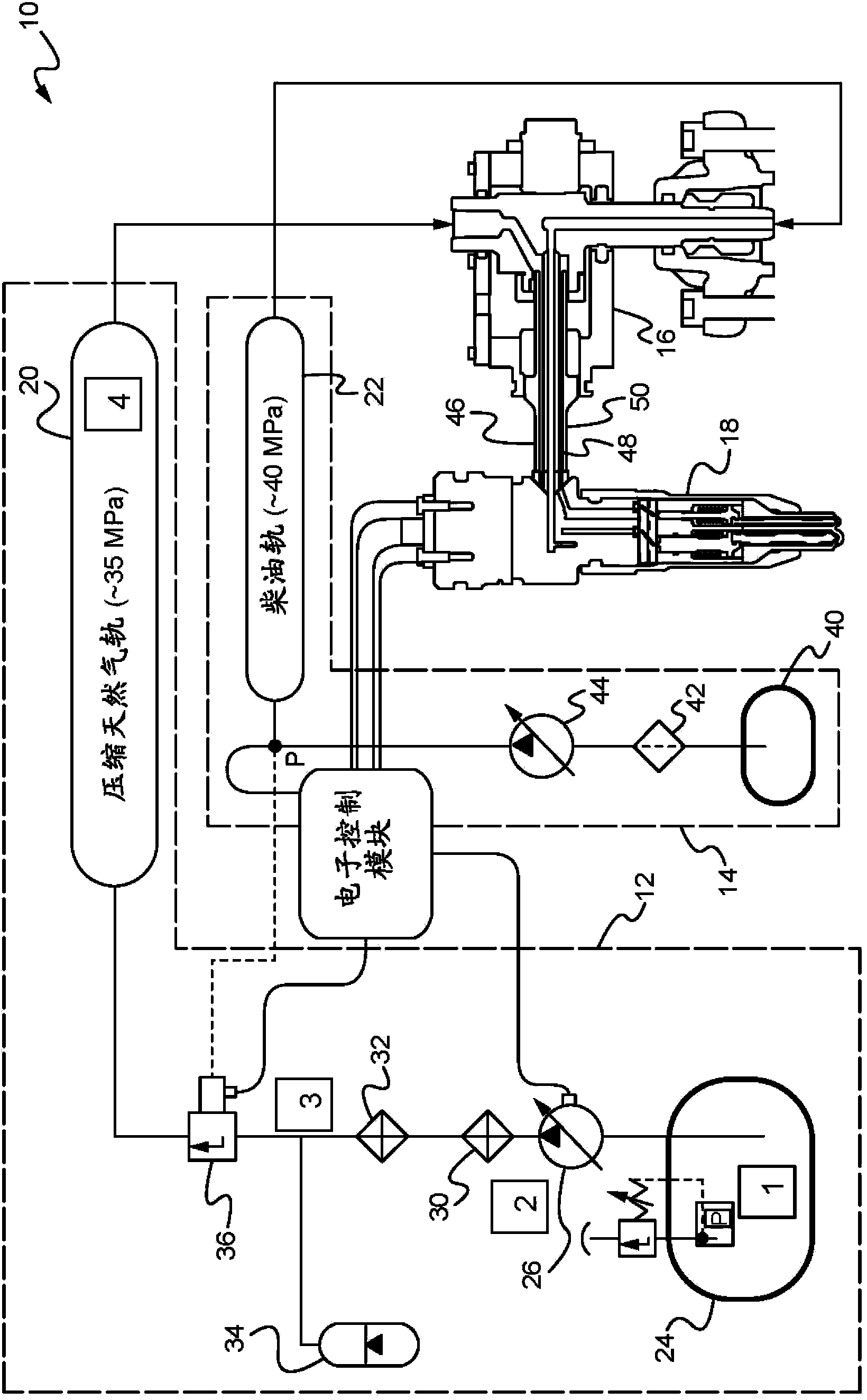
[0017] figure 1 is a schematic diagram of a natural gas and diesel feed system 10 for use in a dual fuel engine. The illustrated system 10 includes a natural gas supply system, generally indicated at 12 , a diesel supply system, generally indicated at 14 , and a plurality of coaxial quill assemblies 16 in fluid communication with a corresponding number of dual fuel injectors 18 . The natural gas supply system 12 and the diesel supply system 14 respectively pass through the natural gas rail 20 and the diesel rail 22 (such as figure 1 shown) supply natural gas (NG) and diesel to the dual fuel injector 18, respectively.

[0018] The...


PUM


Abstract

The invention relates to a diesel fuel leakage control system for a dual fuel injector. The system for controlling leakage of diesel fuel into the natural gas side of a dual fuel injector during low pressure natural gas conditions comprises a leakage control valve that blocks the diesel fuel line during very low natural gas line pressure conditions, including start-up and limp-home mode conditions.

Description

technical field [0001] The present invention relates generally to dual fuel engines, and more particularly to a system for controlling leakage of diesel fuel to the natural gas side of a dual fuel injector. Background technique [0002] In a diesel internal combustion engine, gases are introduced into each combustion chamber (cylinder) during the intake stroke and then compressed during the compression stroke. This compression raises the gas temperature so that when the diesel is introduced into the cylinder at the top of the compression stroke, the diesel vaporizes and ignites in a process called compression ignition. The ignited diesel undergoes rapid expansion, driving the piston down during the power stroke. Exhaust gases are expelled during the exhaust stroke and the four-stroke diesel cycle begins again. [0003] Diesel engines have high reliability, mainly due to the absence of the electronically controlled ignition system necessary for gasoline engines, and general...

Claims


Application Information

Patent Timeline
Patent Type & Authority Applications(China)
IPC IPC(8): F02M63/00
CPCF02M2200/44F02M63/00F02D19/08F02M59/44F02M43/04F02D19/0605F02D19/0647F02D19/0694F02D19/105F02M2200/28F02M2200/18F02M2200/02F02M2200/16F02M63/0056Y10T137/2572Y10T137/0324Y10T137/7837Y02T10/30
Inventor M·F·索马斯H·金
Owner CATERPILLAR INC
Why Eureka
Try Eureka