Axle-flow fan blade

A technology of axial flow blades and blades, which is applied to parts of pumping devices for elastic fluids, non-variable pumps, machines/engines, etc. It can reduce the noise of eddy current, improve the shedding of vortex and improve the efficiency.

Active Publication Date: 2014-02-12
GREE ELECTRIC APPLIANCES INC
View PDF6 Cites 7 Cited by
  • Summary
  • Abstract
  • Description
  • Claims
  • Application Information

AI Technical Summary

Problems solved by technology

In addition, near the suction front edge of the blade, boundary layer separation occurs, resulting in vortices
In short, the above two situations will lead to eddy curr

Method used


Image

  • Axle-flow fan blade
  • Axle-flow fan blade
  • Axle-flow fan blade

Examples


Embodiment Construction

[0035] In order to make the objectives, technical solutions, and advantages of the present invention clearer, the following describes the axial fan blade of the present invention in further detail with reference to the accompanying drawings and embodiments.

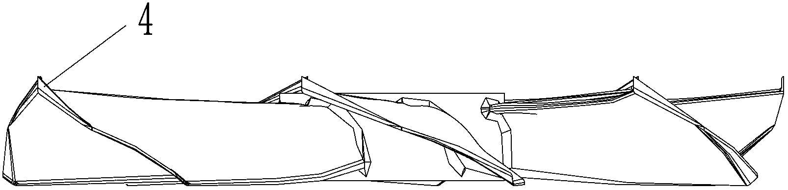
[0036] First, the blade of the axial flow blade is described. The edge of the blade facing the direction of rotation is the leading edge, the edge that faces away from the direction of rotation is the trailing edge, the radially outward edge of the blade is the outer edge, and both sides of the blade They are the pressure surface on the air outlet side and the suction surface on the air inlet side.

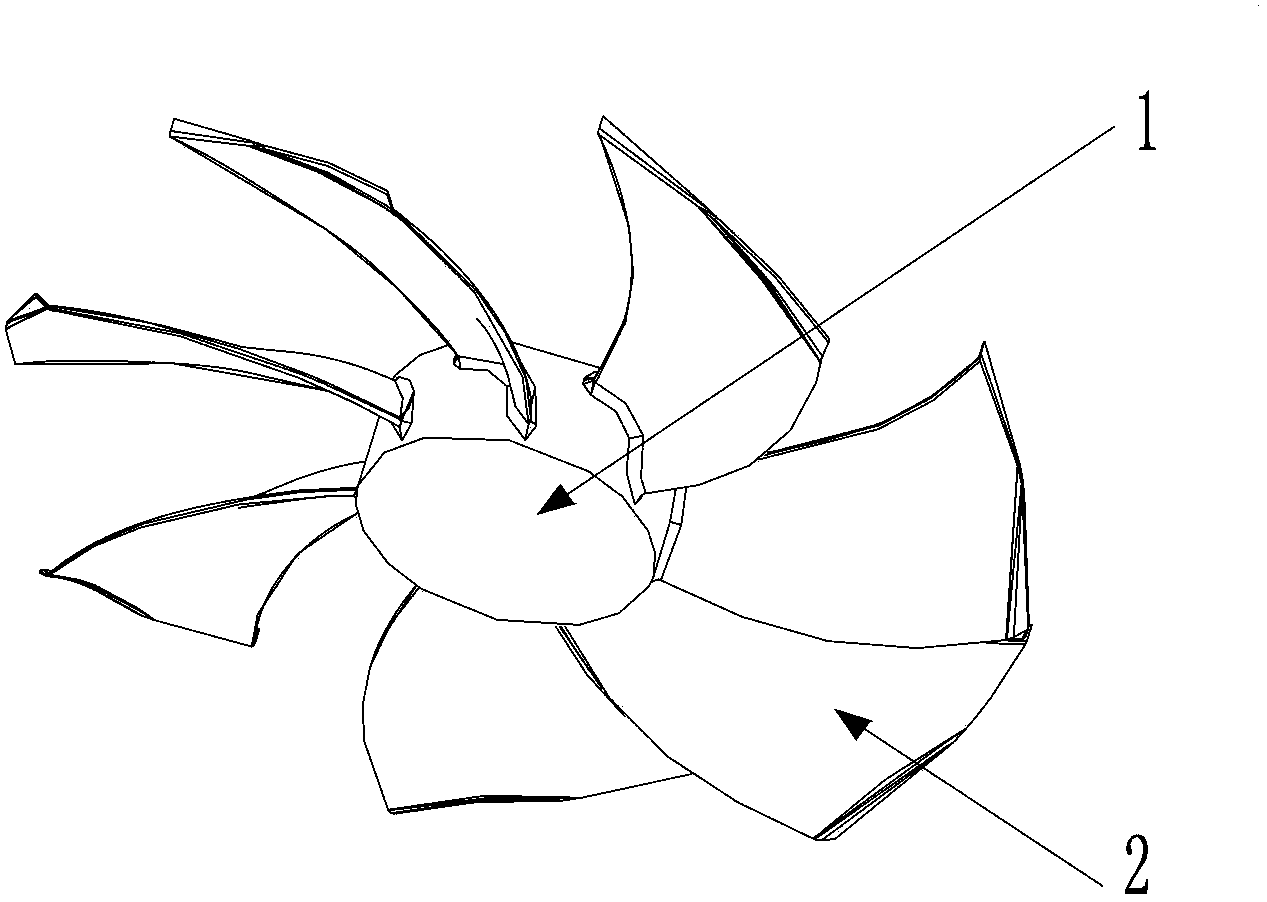
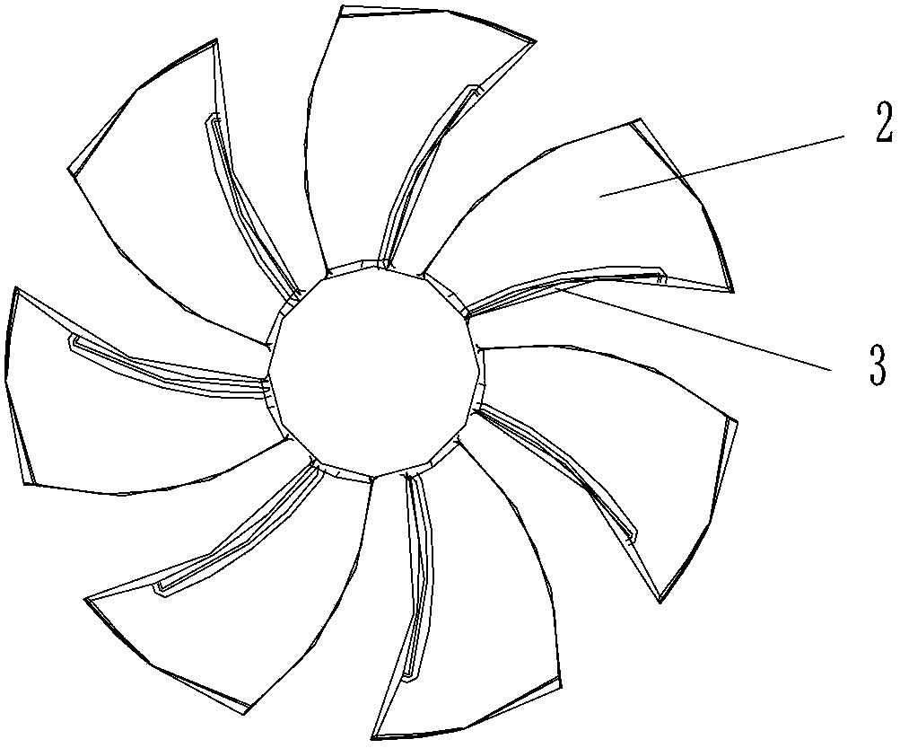
[0037] Reference Figure 1 to Figure 11 , The axial flow blade of the present invention includes a hub 1. A plurality of blades 2 are axially distributed on the hub 1. Each blade 2 has the same shape and is centered on the axis of rotation of the axial flow blade. The two sides of the blade 2 are the pressure surface T and the suc...


PUM


Abstract

The invention discloses an axle-flow fan blade comprising a hub and blades connected to the hub. Each blade is of a pressure face on the outlet side and a suction face on the intake side, multiple fold sections are arranged at the outer edges, extending outwards, of the blades, and the fold sections extend to the suction faces from the pressure faces. The multiple fold sections are arranged at the outer edges of the blades, the front edges of the blades are provided with recesses, the mode of air flowing through the outer edges and the front edges of the blades is changed, 'drain' of air at the outer edges of the blade is reduced, the drop mode of vortexes at the front edges of the blades can be improved, the efficiency of the fan is improved, and vortex noises (broad-band noises) of the fan blade are reduced..

Description

technical field [0001] The invention relates to a fan blade, in particular to an axial flow fan blade. Background technique [0002] In the outdoor unit of the air conditioner or other ventilation devices, various axial flow blades are usually used in order to realize air circulation. The basic structure of the existing mainstream wind blades is the hub as the rotating shaft and radially arranged on the outer periphery of the center. Composed of multiple blades, driven by a motor to rotate, air flows in from the front edge of the blade, and blows out from the rear edge of the blade after the blade is boosted, thus forming a pressure surface and a suction surface; the existing axial flow blades are running During the process, a low-pressure area, that is, a vortex, is often generated in the middle part of the blade tip on the suction surface. The vortex is mainly caused by the flow of air from the high-pressure area of ​​the pressure surface of the blade to the low-pressure a...

Claims


Application Information

Patent Timeline
IPC IPC(8): F04D29/32F04D29/38
Inventor 曹锋刘中杰
Owner GREE ELECTRIC APPLIANCES INC
Why Eureka
Try Eureka