Clamping member

A technology for clamping parts and engaging pieces, applied in the directions of threaded fasteners, connecting components, mechanical equipment, etc., can solve the problems of interference with the base end of the engaging piece, breakage, damage, etc. The effect of equipment cost and manufacturing cost

Active Publication Date: 2014-02-12
YAZAKI CORP
View PDF12 Cites 2 Cited by
  • Summary
  • Abstract
  • Description
  • Claims
  • Application Information

AI Technical Summary

Problems solved by technology

[0003] However, when the clamping member is mounted on the stud bolt, once the positions of the two are misaligned, the front end of the stud bolt will interfere with the base end of the engaging piece.
Then, the engaging piece is accidentally damaged or damaged due to impact when it interferes with the stud bolt, so that sufficient engagement force with the stud bolt cannot be achieved.

Method used


Image

  • Clamping member
  • Clamping member
  • Clamping member

Examples


Embodiment Construction

[0058] Hereinafter, embodiments of the present invention will be described with reference to the drawings.

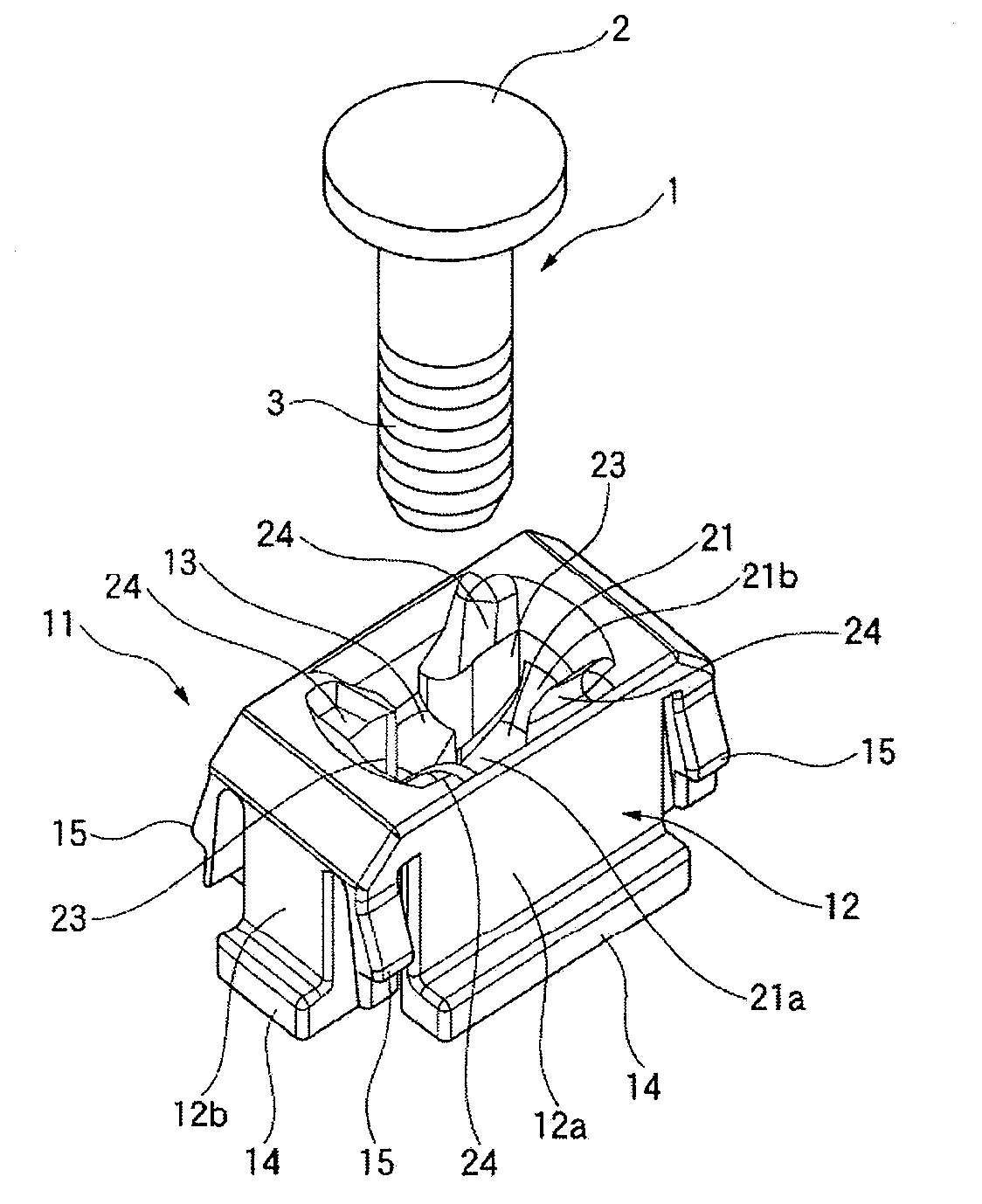
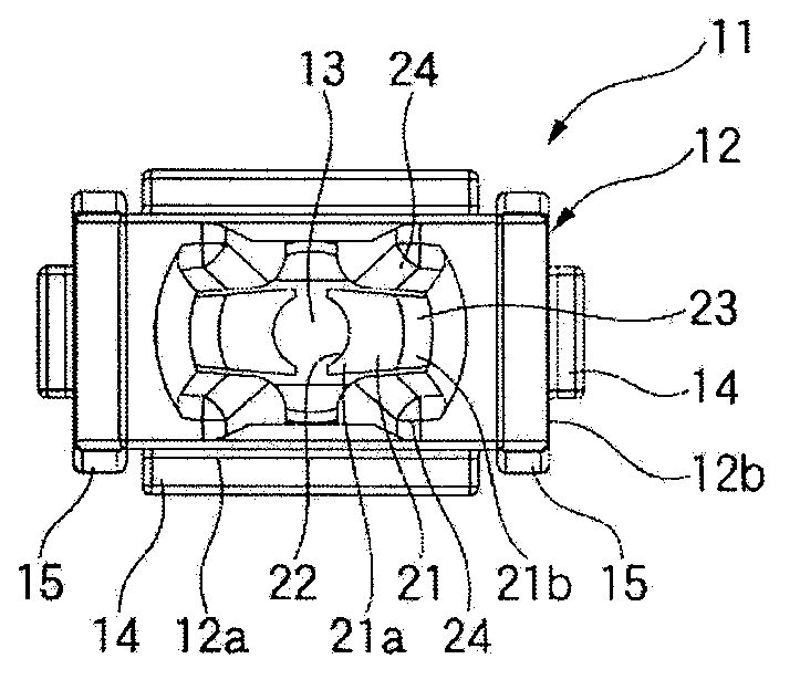
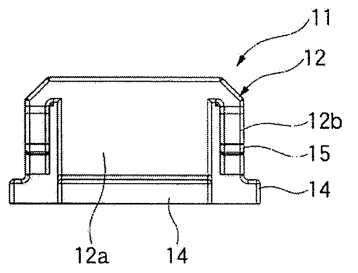
[0059] figure 1 It is a perspective view of the clamp and the stud bolt of this embodiment. Fig. 2 is a schematic diagram of the clamping part of this embodiment, wherein Fig. 2(a) is a top view, Fig. 2(b) is a side view, Fig. 2(c) is a bottom view, and Fig. 2(d) is an end view. 3( a ) is a cross-sectional view along the side of the clip according to this embodiment, and FIG. 3( b ) is an enlarged cross-sectional view of a part of the cross-sectional view in FIG. 3( a ). Figure 4 It is a sectional view along the end surface of the clip of this embodiment.

[0060] Such as Figure 1 ~ Figure 4 As shown, the clip 11 of the present embodiment has a box-shaped main body 12 surrounded by wall portions 12a, 12b. The clip 11 is a member formed integrally with resin by injecting resin into a mold. The insertion portion 13 is disposed through the center of the main body po...


PUM


Abstract

The invention relates to a clamping member capable of inhibiting device costs and production costs, inhibiting damages during the clamping connection with the bolt, and being well clamped with the bolt. A main body (12) of the clamping member is provided with an opening part (23), which is disposed in a base end part of a clamping sheet (21). A bolt (1) can be inserted in the opening part (23). Two sides of the opening part (23) of the clamping sheet (21) are provided with protective wall parts (21), the thicknesses of which are greater than that of other parts of the main body (12).

Description

technical field [0001] The present invention relates to a clamp mounted on a bolt provided on a body of an automobile or the like. Background technique [0002] Generally, when wiring a wire harness to a body of an automobile, a clamp molded integrally or separately from a synthetic resin with a binding band for binding the wire harness or the like is used (see Patent Documents 1 to 4). Such a clamp has a plurality of engaging pieces, and the clamp is fixed to the studs by engaging the front ends of the engaging pieces with the studs protruding from the vehicle body. [0003] However, when the clip is mounted on the stud bolt, if the positions of the two are shifted from each other, the front end of the stud bolt will interfere with the base end portion of the engaging piece. Then, the engaging piece is accidentally damaged or damaged due to an impact when it interferes with the stud bolt, so that sufficient engagement force with the stud bolt cannot be achieved. [0004] ...

Claims


Application Information

Patent Timeline
Patent Type & Authority Applications(China)
IPC IPC(8): F16B37/08
Inventor 龟之上正义上垣内俊吾
Owner YAZAKI CORP
Why Eureka
Try Eureka