Stepless speed variator
A technology of stepless speed change and gearbox, applied in the direction of transmission parts, elements with teeth, belts/chains/gears, etc., can solve the problem of poor cooling effect of the sliding plate 153, and achieve the effect of uniform cooling effect
- Summary
- Abstract
- Description
- Claims
- Application Information
AI Technical Summary
Problems solved by technology
Method used
Image

Examples
Embodiment Construction
[0018] The foregoing and other technical contents, features and effects of the present invention will be clearly presented in the following detailed description of two preferred embodiments with reference to the accompanying drawings.
[0019] Before the present invention is described in detail, it should be noted that in the following description, similar elements are denoted by the same reference numerals.
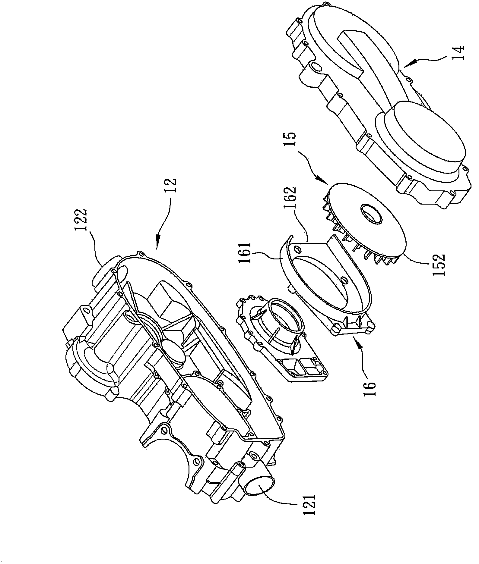
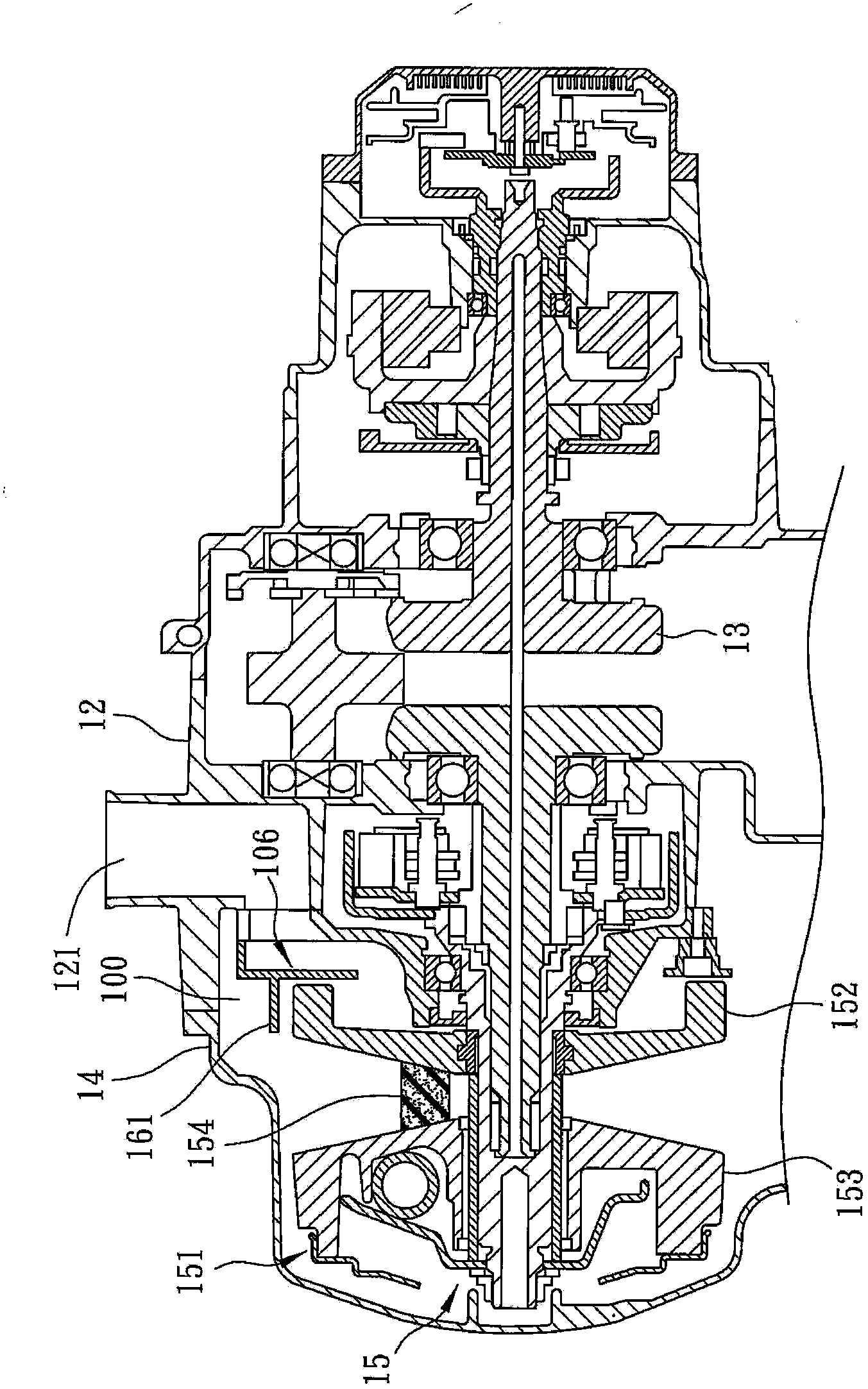
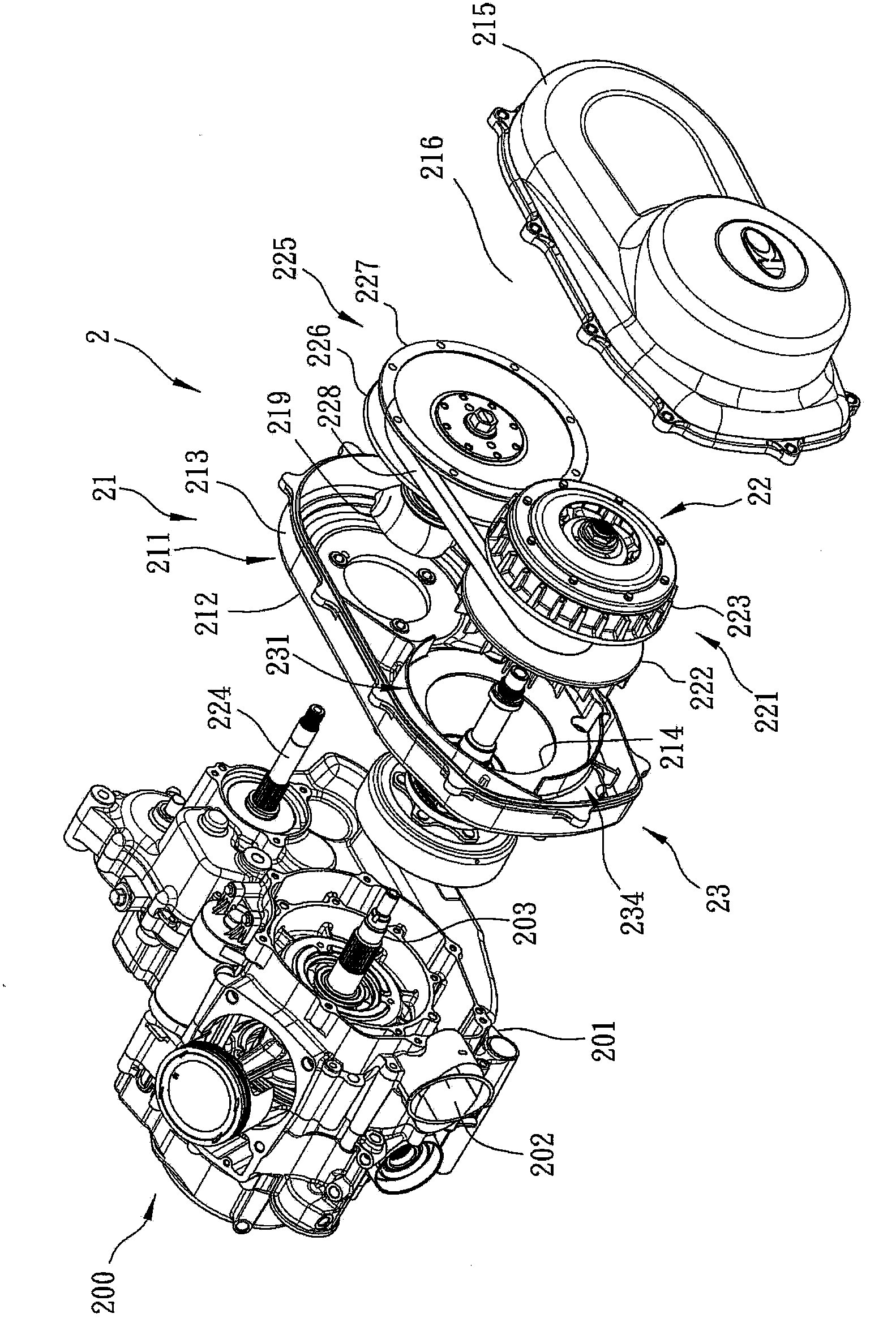
[0020] refer to image 3 , 4 , the first preferred embodiment of the continuously variable transmission device 2 of the present invention is applicable to an engine 200 of a vehicle, and the engine 200 includes a crankcase 201 formed with an air inlet 202, and a main shaft passing through the crankcase 201 203. Figure 4 The middle arrow F represents the forward direction of the engine 200, and Figure 4 The middle arrow F represents the rearward direction of the engine 200 .
[0021] The continuously variable transmission device 2 includes a gearbox 21 combined with...
PUM
 Abstract
Description
Claims
Application Information