A reverse sealing device for a valve stem with a fixed stroke

A reverse seal, stroke valve technology, applied in the direction of the valve device, shaft seal, cock including the cut-off device, etc., can solve the problems of valve stem and bonnet leakage, leakage, short service life, etc., and achieve the effect of reliable sealing performance

Active Publication Date: 2016-01-20
KEKE VALVE ZHEJIANG
View PDF6 Cites 0 Cited by
  • Summary
  • Abstract
  • Description
  • Claims
  • Application Information

AI Technical Summary

Problems solved by technology

However, when the sealing packing is worn out after a long time of use, the upward thrust of the medium pressure on the stuffing box will not be enough to compress the sealing packing, resulting in consistent leakage and short service life.
Especially when ball valves, plug valves, butterfly valves or hidden stem gate valves and other valves with no lifting stroke of the valve stem are opened and closed, the valve stem only rotates without lifting movement, and the cavity seal between the valve stem and the bonnet is completely dependent on the packing. Sealing, after a long time of opening and closing movement, the packing is easily worn or loosened, causing leakage between the valve stem and the valve cover, and the sealing performance is unreliable

Method used


Image

  • A reverse sealing device for a valve stem with a fixed stroke
  • A reverse sealing device for a valve stem with a fixed stroke

Examples


Embodiment Construction

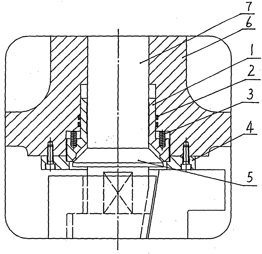
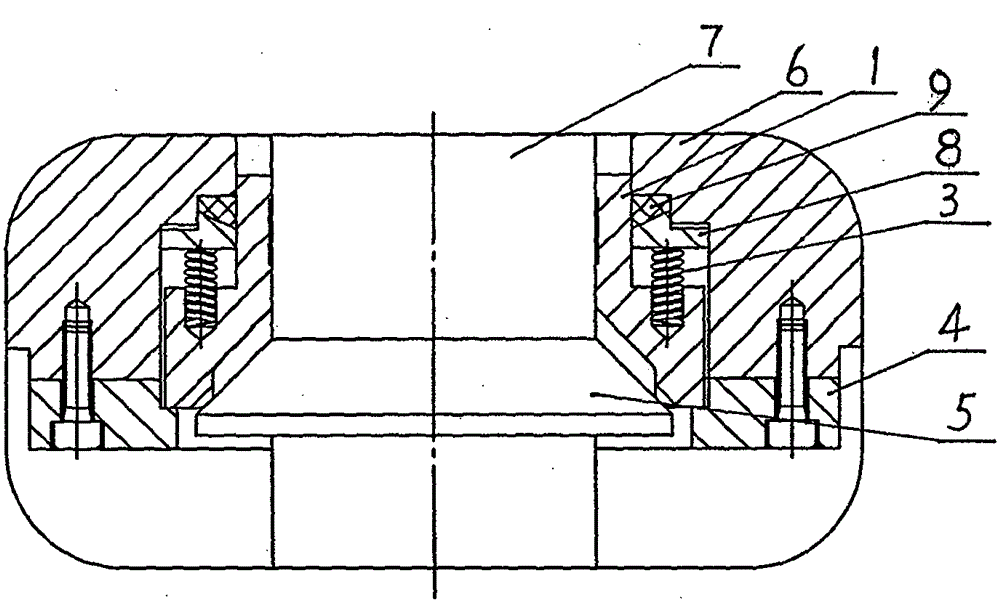
[0010] Such as figure 1 The reverse sealing device of the fixed-stroke valve stem shown includes a valve cover 6 and a valve rod 7, and a reverse sealing device is provided in the middle cavity between the valve cover 6 and the valve rod 7, and the reverse sealing device consists of an upper sealing seat 1, The pre-tightening spring 3 and the lower baffle 4 are composed. The upper sealing seat 1 is composed of two parts: the upper small-diameter outer cylinder and the lower large-diameter outer cylinder. That is, the upper sealing seat 1 is composed of two cylinders with different outer diameters. The upper cylinder The outer diameter of the cylinder is smaller than the outer diameter of the lower cylinder. The outer cylindrical surfaces of the small-diameter outer cylinder and the large-diameter outer cylinder respectively cooperate with the small round hole and the inner wall of the large round hole in the valve cover 6 for dynamic sealing, and the pre-tension spring 3 is in...


PUM


Abstract

The invention relates to a back seal device of a fixed-stroke valve rod. A valve comprises a valve cover and the valve rod, and the back seal device is arranged in a middle cavity between the valve cover and the valve rod. The back seal device is composed of an upper seal base, pre-tightened springs and a lower baffle, wherein the upper seal base is composed of an upper small-diameter outer cylinder and a lower large-diameter outer cylinder, the outer cylinder surface of the small-diameter outer cylinder and the outer cylinder surface of the large-diameter outer cylinder are in dynamic seal fit with the inner round wall of a small round hole and the inner round wall of a large round hole in the valve cover, the pre-tightened springs are arranged between an outer step of the upper seal base and a radial inner step of the large round hole in the valve cover, an inner hole of the upper seal base is in movable fit with the valve rod, and the lower portion of the inner hole of the upper seal base is provided with a circular conical surface; the valve rod is provided with an outer circular conical surface protruding shoulder matched with the circular conical surface of the inner hole of the upper seal base, the outer edge of the lower end face of the upper seal base is pressed on the upper plane of the lower baffle, and the lower baffle is fixedly arranged on the inner cavity wall of the valve cover through screws. The back seal device has the advantages of achieving automatic compensation for a sealing surface, reliable sealing performance and the like.

Description

technical field [0001] The invention relates to the field of valves, in particular to a valve cavity sealing device. The present invention is applicable to the sealing device of the middle cavity of valves such as ball valves, plug valves, butterfly valves, hidden stem gate valves and the like. Background technique [0002] Existing valves generally adopt a packing seal structure between the valve stem and the valve cover. This structure will cause wear to the packing during the opening and closing process of the valve, and leakage between the valve stem and the valve cover will easily occur after long-term use. For example, the bonnet pressure self-sealing gate valve whose patent number is ZL201020675229.2, the bonnet is sealed and welded on the valve body, a stuffing box is set between the bonnet and the valve stem, and a sealing packing is arranged between the stuffing box and the valve stem. The lower end of the stuffing box has a bell mouth facing the inner cavity of t...

Claims


Application Information

Patent Timeline
Patent Type & Authority Patents(China)
IPC IPC(8): F16K1/32F16K1/46F16K1/34
CPCF16K1/2266F16K5/0285F16K5/0485F16K5/0694F16K41/02
Inventor 邹新鹏胡隆峰郑瑞建
Owner KEKE VALVE ZHEJIANG
Why Eureka
Try Eureka