
Flow regulating valve

A flow control valve and valve body technology, applied in valve details, multi-port valves, valve devices, etc., can solve the problems of inability to control the flow of the primary and secondary circuits, troublesome maintenance and replacement of parts, and large space occupation. Small footprint, extended service life, and low cost effects

Active Publication Date: 2014-02-12
SHAOXING SANHUA NEW ENERGY AUTOMOTIVE COMPONENTS CO LTD
View PDF6 Cites 14 Cited by
  • Summary
  • Abstract
  • Description
  • Claims
  • Application Information

AI Technical Summary

Problems solved by technology

[0004] The electric water valve with the above structure has the following defects in the actual use process: the flow of the primary circuit and the secondary circuit cannot be controlled in the prior art, and other flow regulating valves must be installed when the flow in the circuit needs to be controlled. In this way, not only the cost High, takes up a lot of space, and it will be more troublesome to repair and replace parts in the future

Method used


Image

  • Flow regulating valve
  • Flow regulating valve
  • Flow regulating valve

Examples


Embodiment Construction

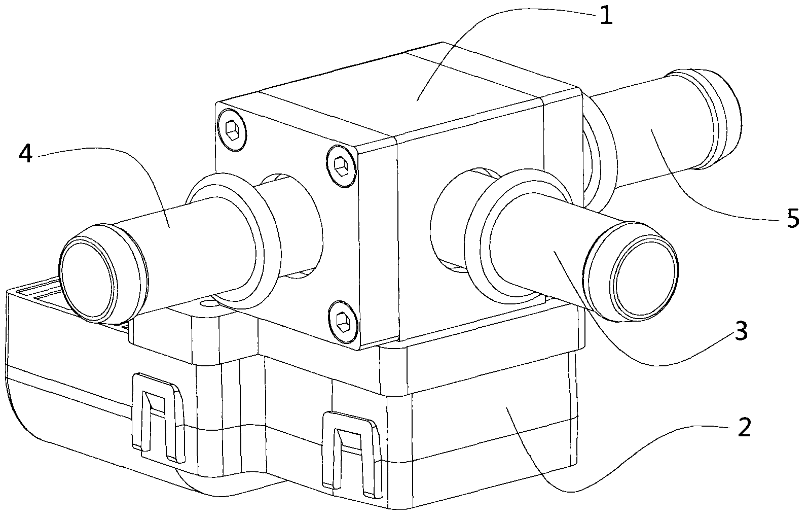
[0026] In the process of specific use of the flow regulating valve of the present invention, the stepper motor drives the vanes arranged in the valve body to swing as required and can stay at any position, thereby controlling the fluid flowing in from the inlet pipeline from the first to the second according to a certain flow ratio. An outlet line and a second outlet line flow out.

[0027] The specific implementation manners of the present invention will be further described in detail below in conjunction with the accompanying drawings.

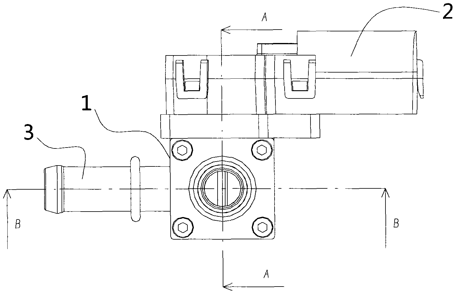
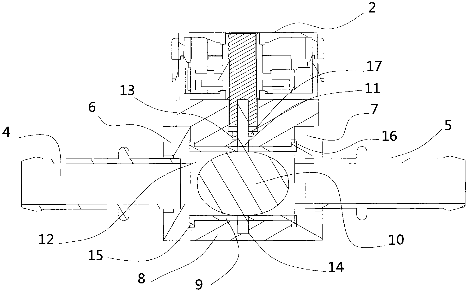
[0028] figure 1 is a perspective view of the first embodiment of the flow regulating valve of the present invention, figure 2 is the front view of the first embodiment of the present invention, image 3 yes figure 2 A-A sectional view of the first embodiment shown, Figure 4 yes figure 2 B-B sectional view of the first embodiment of the flow regulating valve shown, Figure 5 is a blade sectional view of the first embodiment of the p...


PUM


Abstract

The invention discloses a flow regulating valve comprising a valve body component and an electric actuator fixed on the valve body component. The valve body component comprises a stepping motor, the valve body component comprises a valve body, an inlet pipeline, a first outlet pipeline and a second outlet pipeline, and inlet and a through hole are formed in the valve body, a sleeve is arranged in the through hole, blades used for distribution and drainage and a rotating shaft used for connecting the blades with the electric actuator and driving the blades to swing are arranged in the sleeve, the rotating shaft penetrates a shaft hole to extend into the through hole in the valve body and is fixedly connected with the blades, and the shaft hole is formed in the valve body to allow the rotating shaft to penetrate. The flow regulating valve has the advantages that flow of a loop can be controlled, distribution of fluid flow ratios of a first fluid passage and a second fluid passage in the pipelines is achieved, sealing performance between the blades and the sleeve is good, the blades and the through hole are all not easy to wear, and the flow regulating valve is simple in structure, low in cost, and small in occupied space.

Description

technical field [0001] The invention relates to the technical field of fluid control, in particular to a flow regulating valve, which is a flow regulating valve capable of adjusting the flow ratio and reversing of two outlet passages. Background technique [0002] In the automotive thermal management system, it is often necessary to use a three-way flow regulating valve to switch the flow path. The application of the three-way valve can effectively streamline the pipeline and simplify the complicated pipeline. However, the current three-way flow regulating valve can only be used simply. The switching of the flow path cannot adjust the flow ratio of the two flow paths. [0003] For example, in a flow regulating valve is disclosed comprising a body defining a fluid inlet conduit leading to two fluid outlet conduits forming a junction where a butterfly valve directs fluid primarily to the first Actuated between a first abutment of an outlet conduit and a second abutment direct...

Claims


Application Information

Patent Timeline
IPC IPC(8): F16K11/052F16K27/02F16K31/04F16K31/53
CPCF16K11/0525F16K27/0227F16K31/041F16K31/535
Inventor 裘浩明尹斌章剑敏王晖
Owner SHAOXING SANHUA NEW ENERGY AUTOMOTIVE COMPONENTS CO LTD
Features
  • Generate Ideas
  • Intellectual Property
  • Life Sciences
  • Materials
  • Tech Scout
  • Unparalleled Data Quality
  • Higher Quality Content
  • 60% Fewer Hallucinations
Learn More