Pipe assembly for the flow of a fluid and of a current and method for assembling such a pipe assembly

A technology of fluid flow and tube assembly, applied in the direction of fluid heaters, pipes/pipe joints/fittings, hoses, etc., can solve the problems of power consumption, low efficiency, heat loss, etc., and achieve low cost and reduce manufacturing costs.

Inactive Publication Date: 2014-02-12
MGI COUTIER SA
View PDF1 Cites 0 Cited by
  • Summary
  • Abstract
  • Description
  • Claims
  • Application Information

AI Technical Summary

Problems solved by technology

[0004] However, the wire 12 emits as much heat towards the external medium as towards the tube 11, which corresponds to a large heat loss
Therefore, the heat transfer from the wire 12 to the fluid has low efficiency, which requires a large consumption of electrical energy

Method used


Image

  • Pipe assembly for the flow of a fluid and of a current and method for assembling such a pipe assembly
  • Pipe assembly for the flow of a fluid and of a current and method for assembling such a pipe assembly
  • Pipe assembly for the flow of a fluid and of a current and method for assembling such a pipe assembly

Examples


Embodiment Construction

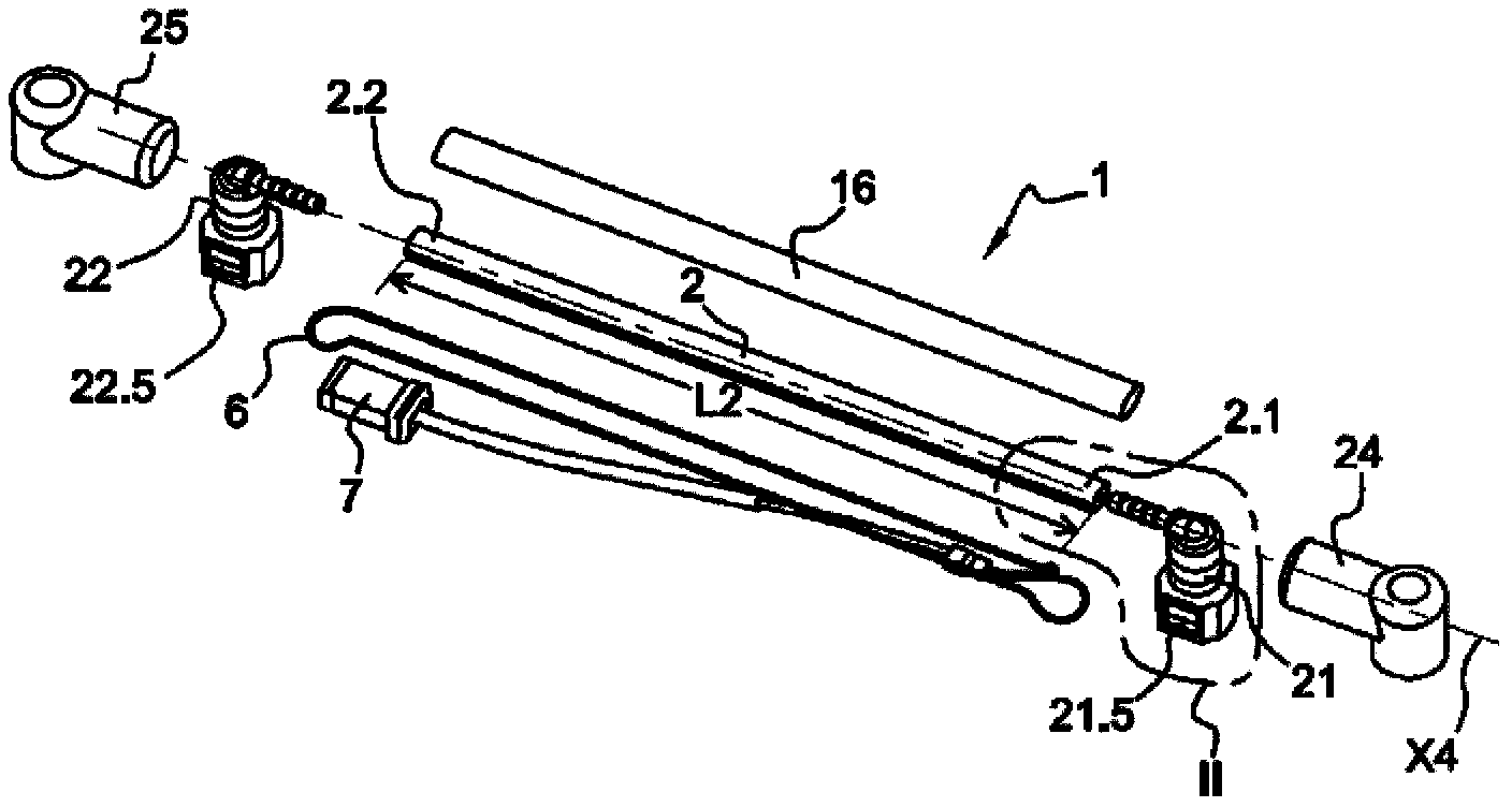
[0069] figure 1 with figure 2 Shown is a tube assembly 1 for fluid flow and electrical current circulation along a tube 2 . In the illustrated example, the fluid is a liquid consisting of an aqueous urea solution, and the electric current has the function of heating the aqueous urea solution as it flows inside the pipe 2 .

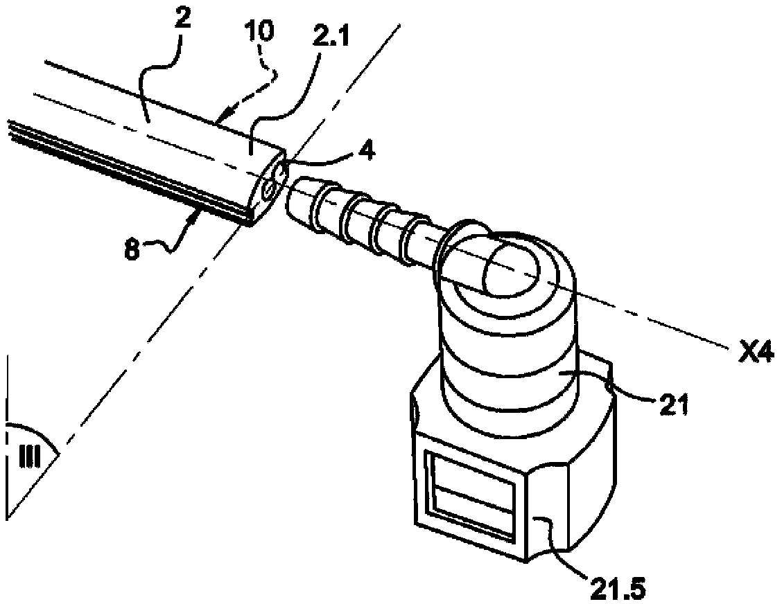
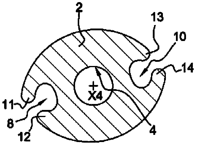
[0070] The tube assembly 1 comprises a tube 2 having an inner conduit 4, such as figure 2 shown. The inner conduit 4 is configured for liquid flow. To this end, the inner conductor 4 leads to the first end 2.1 of the tube 2 and to the second end 2.2 of the tube 2 .

[0071] The tube assembly 1 also includes a wire 6 which is an electrical conductor and has a length greater than that of the tube 2 . The wire 6 is here formed by a resistive wire suitable for converting electric current into heat by means of the Joule effect. The wire 6 here consists of a metallic material. The resistivity of the wire 6 is determined according to the application of t...


PUM


Abstract

This pipe assembly comprises a pipe (2) having an internal duct (4) for the fluid and an electrical wire (6) longer than the pipe (2). The pipe (2) comprises: one or more groove(s) (8, 10) along the pipe (2); at least one lip (11, 12, 13, 14) which extends parallel to a groove (8, 10) and which can be deformed; between a configuration in which the electrical wire (6) can be introduced into the groove (8, 10); and a secondary configuration in which a lip (11, 12, 13, 14) covers the groove (8, 10). The pipe assembly also comprises means for keeping the or each lip (11, 12, 13, 14) in the secondary configuration.

Description

technical field [0001] The present invention relates to a tube assembly for fluid flow and electrical current circulation along the tube. Furthermore, the invention relates to a method for assembling such a tube assembly. [0002] The invention finds application in particular in the automotive sector, especially for heating fluids flowing in pipes. In the event that the vehicle is used in the cold, it may be necessary to heat the fluid being delivered to defrost it. In particular, one of the known problems in the use of aqueous urea (solution aqueuse d'urée) is that it has a freezing point of about -12°C. These freezing limitations lead to expensive, complex reheat system designs and / or energy inefficiencies. Background technique [0003] FR2915185A1 describes a tube 11 having an inner conduit configured for fluid flow. The wire 12 is helically wound around the tube 11 to heat the tube 11 and the fluid flowing therein when the wire 12 is powered. [0004] However, the w...

Claims


Application Information

Patent Timeline
Patent Type & Authority Applications(China)
IPC IPC(8): F16L53/00F16L11/12F16L11/08F16L47/06F16L53/38
CPCF16L53/008F24H9/0005F16L11/127F16L53/38Y10T29/49083
Inventor 尼古拉斯·勒布朗亚尼克·塞泽里亚日夫鲁瓦·迈耶
Owner MGI COUTIER SA
Why Eureka
Try Eureka