Constraining structure with non-linear axial struts

a strut and axial strut technology, applied in the field of balloon catheters, can solve the problems of increasing local force, high dissection rate, and conventional balloon angioplasty not providing strain relief to the vessel wall, so as to facilitate plaque extrusion, minimize vessel trauma, and facilitate plaque extrusion

Active Publication Date: 2015-11-10
TRIREME MEDICAL
View PDF142 Cites 31 Cited by
  • Summary
  • Abstract
  • Description
  • Claims
  • Application Information

AI Technical Summary

Benefits of technology

[0005]According to the present invention, a device that modifies the properties of an angioplasty balloon in order to provide uniform inflation and extraction of longitudinal forces in order to facilitate plaque extrusion and minimize vessel trauma. In the device presented herein, a novel constraining structure prevents non-cylindrical expansion using constraining rings that are spaced apart along the balloon working length leading to creation of small balloon segments (pillows) separates by grooves that facilitate plaque extrusion. The constraining structure also prevents longitudinal elongation of the balloon since it has a structure that shortens during expansion and constrains the balloon in both longitudinal and radial directions.
[0006]Computer simulation shows a decrease in radial forces using a balloon with the constraining structure. The constraining structure causes reduction in the rate of vessel dissections and perforations thru formation of an array of balloon pillows that provide gentle contact with the vessel wall and thru the formation of channels between these pillows that allow plaque flow and strain relief areas in the vessel wall.
[0009]The constraining structure of the present invention takes advantage of the fact that by forcing the balloon into pillows topography the excessive length of the balloon is directed into a three dimensional shape and the surface area of the balloon increases. This mechanism shortens the overall balloon length during inflation and minimized longitudinal vessel stretch. Other devices such as stents or scoring cages that have structures over a balloon are using the balloon as an “activator” or expandable shell designed to increase the diameter of the stent or scoring stent and allow the balloon to inflate in full both radially and longitudinally and are therefore designed to expand as big as the inflated balloon, while the design present herein is made smaller than the inflated balloon, specifically aimed to modify, restrict and control the balloon inflated shape and size.
[0010]The combination of the advantages of the device described herein result in controlled non aggressive and predictable lesion dilation that addresses a major health concern.

Problems solved by technology

Conventional balloon angioplasty does not provide strain relief to the vessel wall and suffer from high rate of dissections.
Other devices, such as cutting balloons and scoring devices (for example U.S. Pat. No. 7,691,119 Farnan) made to address resistant lesions by adding elements that can cut or score into the vessel wall and significantly, increase the local force (“focus force angioplasty”), but do not provide strain relief and gentle contact with the vessel wall.
On the contrary, these devices include aggressive metallic components that are made to break hard plaque and mark their metal footprint on the vessel wall.

Method used


Image

  • Constraining structure with non-linear axial struts
  • Constraining structure with non-linear axial struts
  • Constraining structure with non-linear axial struts

Examples


Embodiment Construction

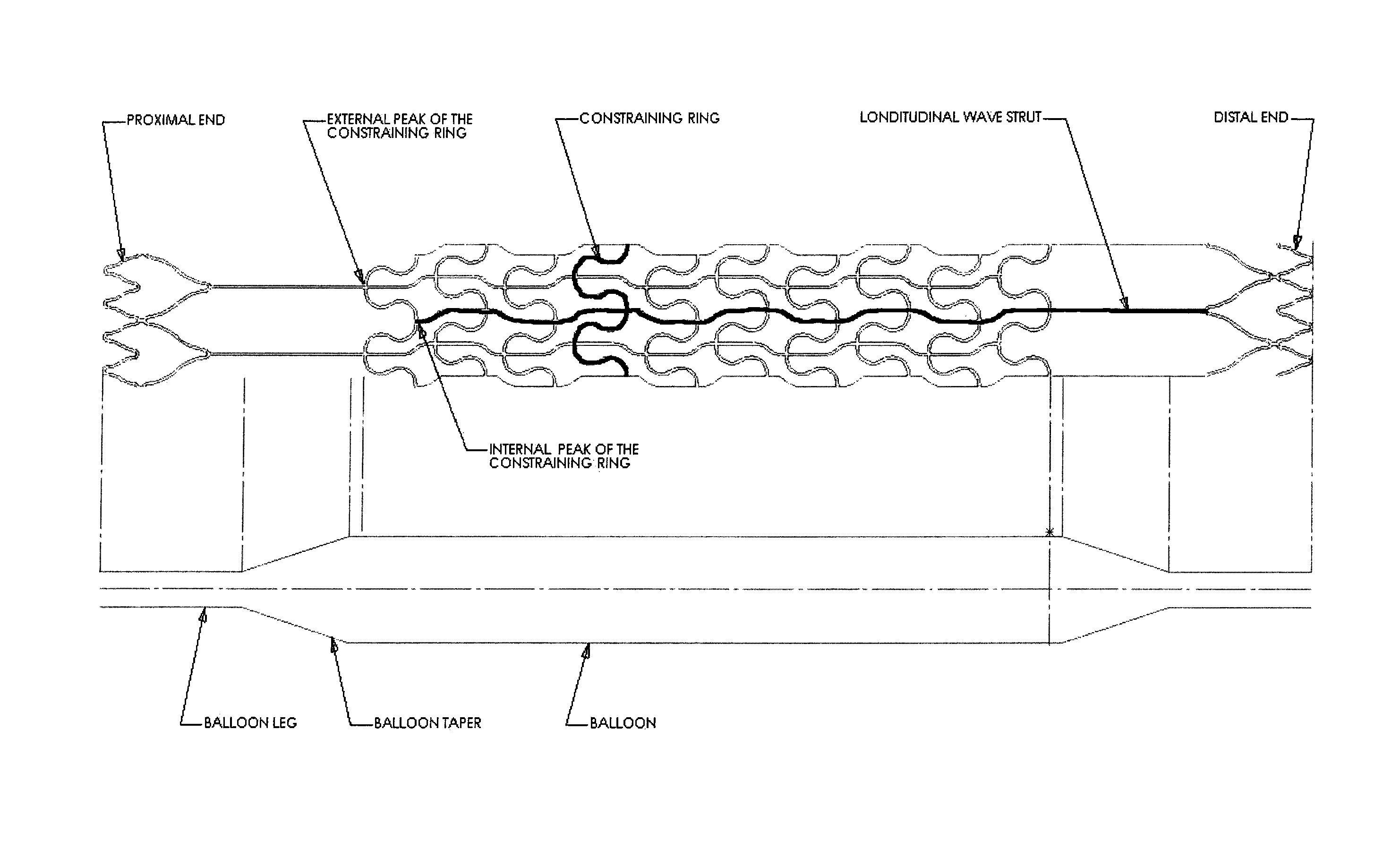
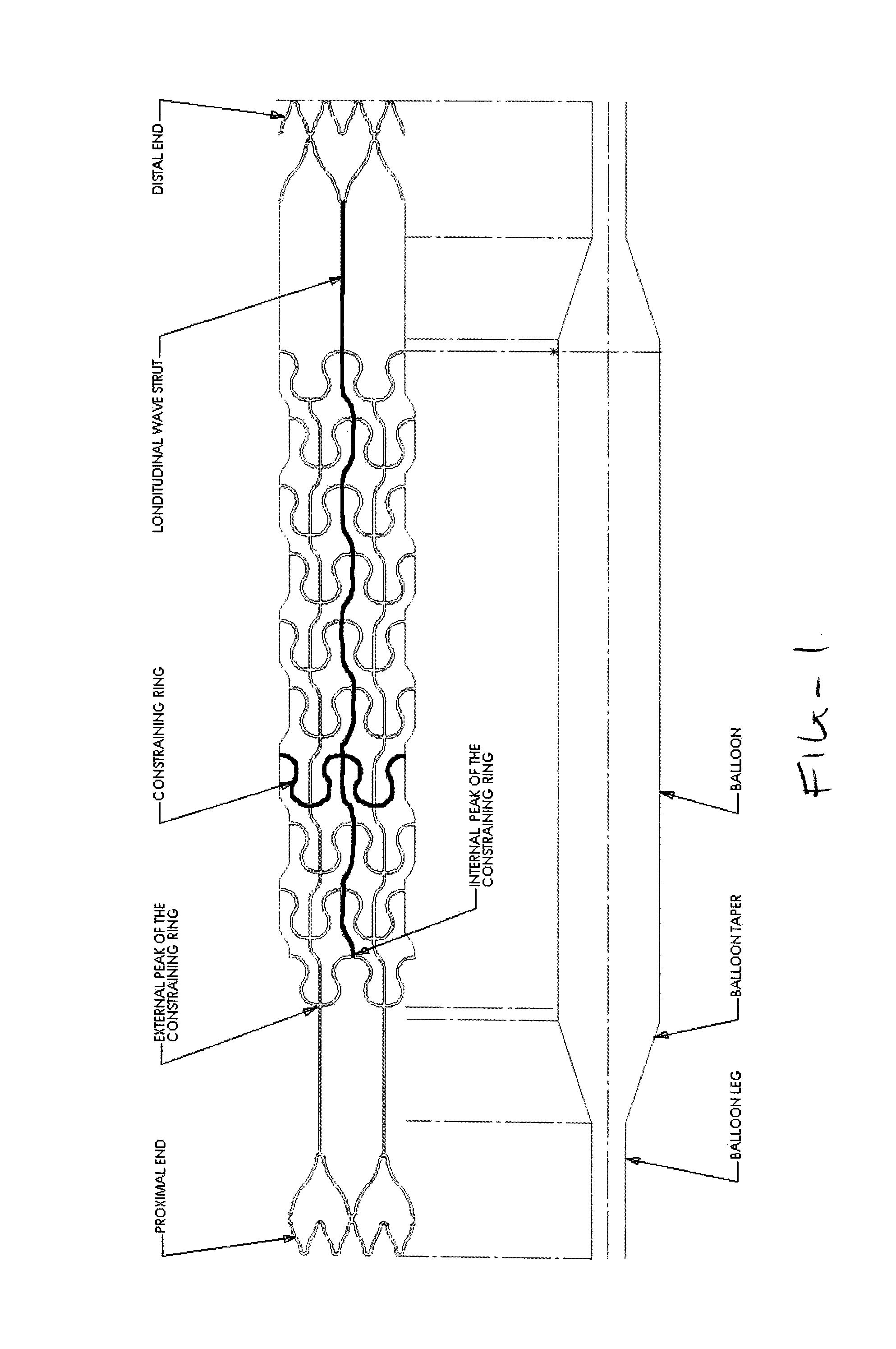
[0015]A balloon catheter comprising a catheter shaft and an inflatable balloon at its distal end and an elastic constraining structure is mounted over the balloon. The constraining structure is made from an elastic material such as Nitinol, elastic polymers or high strength fibers or mesh.

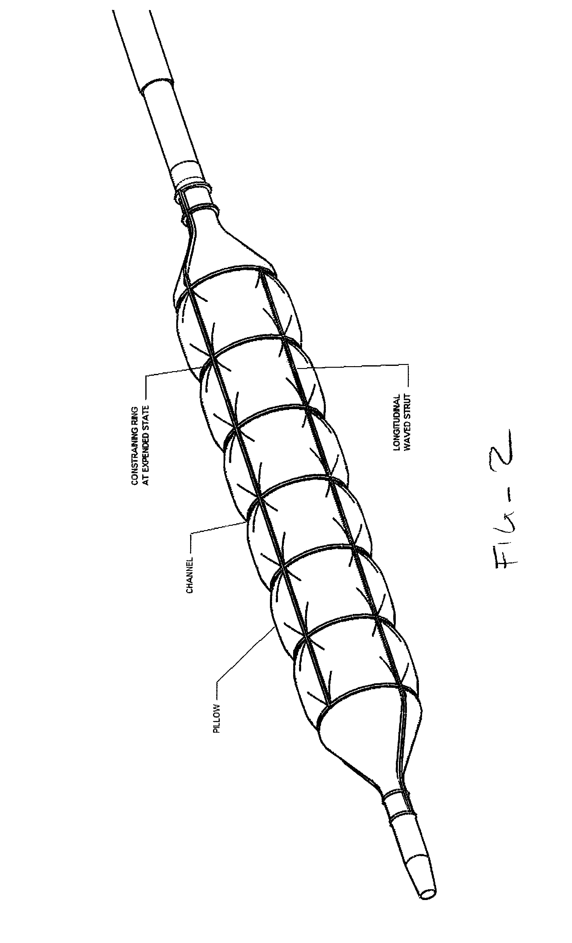
[0016]The device natural configuration is collapsed. Unlike “self-expanding stents,” it is not“self-expanding” but to the contrary “self-closing” prior to expansion the constraining structure is tightly closed on the folded balloon. When the balloon is inflated the constraining structure is expanded by the balloon force up to a diameter smaller than the free inflated diameter of the balloon. The structure will self compress back to a small diameter when the balloon is deflated. Typically the distal end and a proximal end of the constraining structure are fixedly attached to the catheter at both sides of the balloon to prevent it from disengaging with the catheter. Attachment is made by means of adh...


PUM


Abstract

A constraining structure for use with a balloon catheter can include multiple longitudinal struts and multiple, sinusoidal shaped radial rings. The constraining structure can expand to form a pattern of channels including substantially square windows. The constraining structure can modify, restrict, and control a shape and / or size of the balloon when inflated. Inflating the balloon catheter within the constraining structure can provide nonuniform pressure on a vessel wall adjacent the balloon.

Description

[0001]This application claims the benefit of U.S. Provisional Application No. 61 / 596,618, filed Feb. 8, 2012, the entirety of which is incorporated by reference herein.BACKGROUND OF THE INVENTIONField of the Invention[0002]The present invention is a balloon catheter for angioplasty procedures, comprising an elastic constraining structure mounted over the balloon where the structure has a mechanism of expansion to control the balloon inflation.[0003]Conventional angioplasty balloons expand in an artery lesion at the least resistant areas of the lesion causing “dog bone” effect at the lesion ends and overexpansion in the softer areas, resulting in trauma to the vessel wall. Conventional angioplasty is associated with vessel displacement and its main mechanism of action is plaque compression where the vessel is significantly displaced or “pushed out” before reaction force can be generated and plaque compression takes place. During this process the balloon may expand in the axial direct...

Claims


Application Information

Patent Timeline
Patent Type & Authority Patents(United States)
IPC IPC(8): A61B17/50A61B17/3207A61M25/10A61F2/06
CPCA61B17/50A61B17/320725A61M25/104A61M2025/1084A61M25/10A61F2002/91558A61M29/02A61F2002/91566A61F2/915
Inventor FELD, TANHUMKONSTANTINO, EITAN
Owner TRIREME MEDICAL
Why Eureka
Try Eureka