LED energy saving lamp structure
A technology of LED energy-saving lamps and LED light strips, which is applied in lighting applications, lighting and heating equipment, office buildings, etc., can solve the problems of inconvenient disassembly and maintenance, complex internal connection structure, and low structural strength, and achieve Save labor costs and capital costs, strong disassembly and assembly, and high structural stability
- Summary
- Abstract
- Description
- Claims
- Application Information
AI Technical Summary
Problems solved by technology
Method used
Image
Examples
Embodiment 1
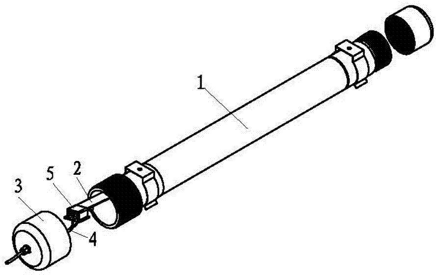
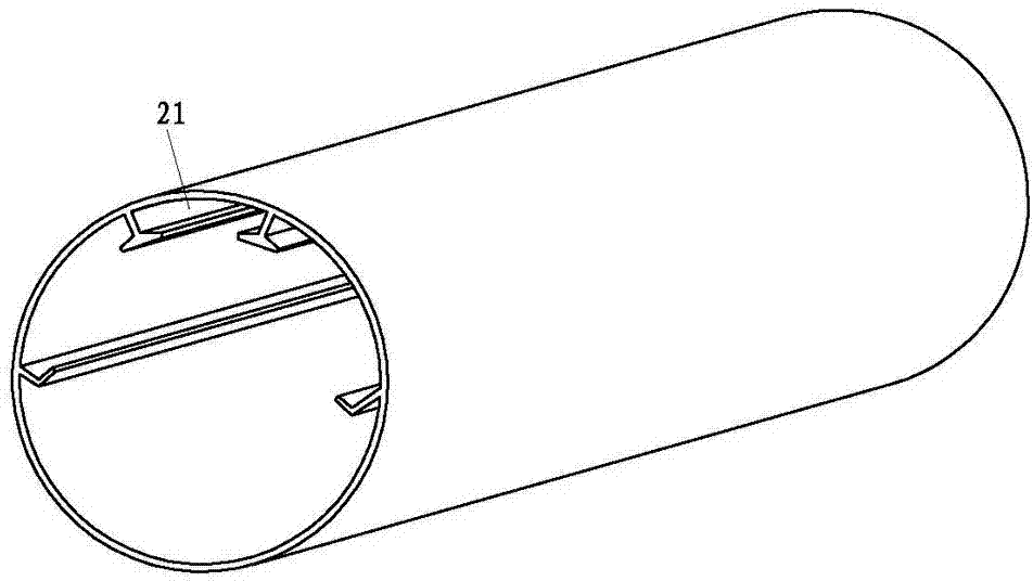
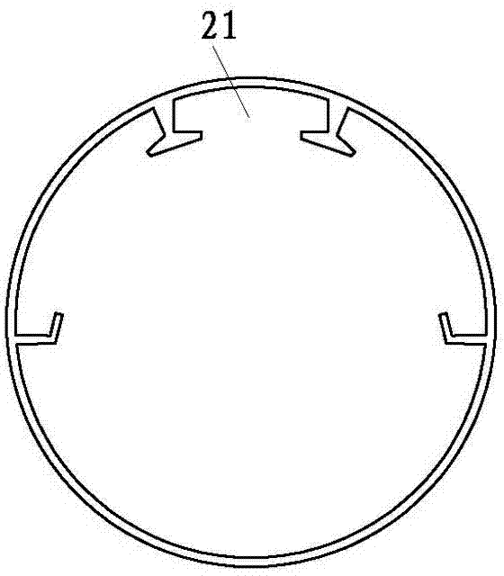
[0042] Such as figure 1 , 2 , 3, 4, 5, 6, 7, 8, 9, 10, 11, 12, an LED energy-saving lamp structure, including an outer cover 1, an LED light bar 2 arranged in the outer cover 1, the outer cover 1 Both ends are provided with end covers 3, and the outer cover 1 is provided with an LED light bar slot 21 for positioning the LED light bar 2, and the positive and negative terminals of one end of the LED light bar 2 are provided with a positive electrode contact 201 and a negative electrode contact 202. The end cover 3 near the end of the LED light bar 2 with the positive electrode contact 201 and the negative electrode contact 202 is provided with a power cord 4 passing through the end cover 3. The positive electrode contact 201 and the negative electrode contact 202 are connected to the power cord 4 is a detachable electrical conduction. The outer cover 1 and the end cover 3 are fixedly connected together by a connecting tube. One end of the connecting tube and the end cover 3 can ...
Embodiment 2
[0051] Such as Figure 13 As shown, the difference from Embodiment 1 is that: between the sheet metal winding plate 513 and the upper groove partition plate 5101, there is provided a sheet metal transfer winding space 512 divided into two or more metal sheet transfer winding sub-spaces 5120 The metal sheet is wound around the plate 514 in the middle.
Embodiment 3
[0053] Such as Figure 14 , 15 , 16, the difference from Embodiment 1 is: the metal sheet mounting structure is different, the metal sheet mounting structure includes a winding plate for forming the insertion groove 51 and for the metal sheet 53 to be wound into the insertion groove 51 511 and a metal sheet winding hole 5110 provided on the winding plate 511. An arc-shaped winding section 5111 is provided on the winding plate 511.
PUM
 Abstract
Description
Claims
Application Information
 - R&D
- Intellectual Property
- Life Sciences
- Materials
- Tech Scout
- Unparalleled Data Quality
- Higher Quality Content
- 60% Fewer Hallucinations
Browse by: Latest US Patents, China's latest patents, Technical Efficacy Thesaurus, Application Domain, Technology Topic, Popular Technical Reports.
© 2025 PatSnap. All rights reserved.Legal|Privacy policy|Modern Slavery Act Transparency Statement|Sitemap|About US| Contact US: help@patsnap.com


