
Method and device for detecting brake air tightness

An air tightness detection and gas path technology, which is applied in the direction of using liquid/vacuum degree for liquid tightness measurement, and by measuring the acceleration and deceleration rate of fluid, etc. The effect of shortening the detection cycle, improving the detection efficiency, and reducing the risk of misjudgment

Inactive Publication Date: 2014-02-12
诸城福田汽车科技开发有限公司 +1
View PDF3 Cites 18 Cited by
  • Summary
  • Abstract
  • Description
  • Claims
  • Application Information

AI Technical Summary

Problems solved by technology

[0004] The invention provides a brake air tightness detection method and device to solve the problem that the air leakage of the vehicle brake system cannot be accurately detected in the prior art

Method used

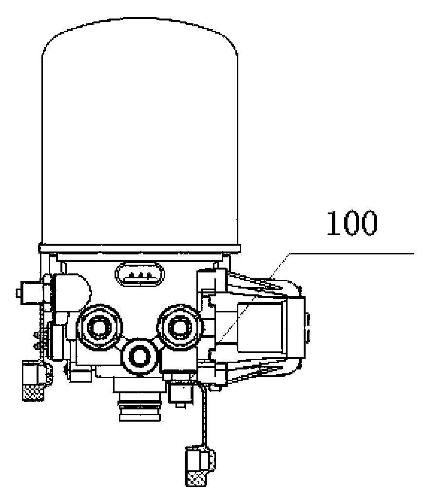

Image

  • Method and device for detecting brake air tightness
  • Method and device for detecting brake air tightness
  • Method and device for detecting brake air tightness

Examples


Embodiment Construction

[0034] Embodiments of the present invention are described in detail below, examples of which are shown in the drawings, wherein the same or similar reference numerals designate the same or similar elements or elements having the same or similar functions throughout. The embodiments described below by referring to the figures are exemplary and are intended to explain the present invention and should not be construed as limiting the present invention.

[0035] In describing the present invention, it is to be understood that the terms "central", "longitudinal", "transverse", "front", "rear", "left", "right", "vertical", "horizontal", The orientations or positional relationships indicated by "top", "bottom", "inner", "outer", etc. are based on the orientations or positional relationships shown in the drawings, and are only for the convenience of describing the present invention and simplifying the description, rather than indicating or implying the It should not be construed as li...


PUM


Abstract

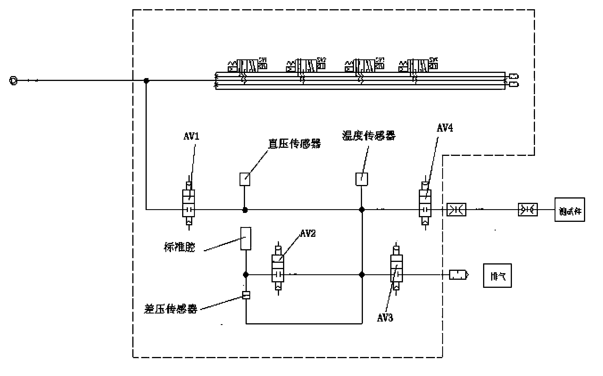
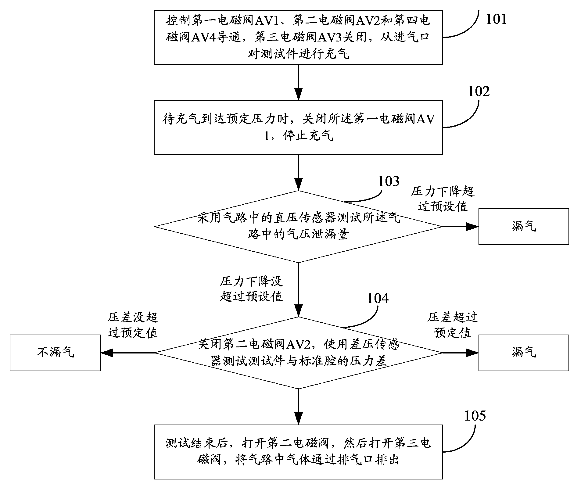
The invention provides a method and device for detecting brake air tightness. The device comprises an air inlet, an exhaust port, a test port, a first electromagnetic valve, a second electromagnetic valve, a third electromagnetic valve, a fourth electromagnetic valve and a direct voltage sensor. The method includes the steps that the first electromagnetic valve, the second electromagnetic valve and the fourth electromagnetic valve are controlled to be connected, the third electromagnetic valve is closed, and then a test piece is inflated from the air inlet; the first electromagnetic valve is closed when the test piece reaches preset pressure after being inflated; the direct voltage sensor is utilized to test air pressure leakage amount in an air path, and if pressure drop in preset time exceeds a preset pressure value, it is determined that the test piece leaks; if pressure drop in the preset time does not exceed the preset pressure value, the second electromagnetic valve is closed, and a differential pressure sensor is utilized to test the pressure difference between the test piece and a standard cavity, if the pressure difference is smaller than the preset pressure value, the test piece does not leak, and if the pressure difference is larger than the preset pressure value, the test piece leaks. According to the method and device, air leakage detection efficiency of the air path is improved, and detection periods are shortened.

Description

technical field [0001] The invention relates to the technical field of automobile testing, in particular to a method and device for detecting brake air tightness. Background technique [0002] In the vehicle test, the vehicle manufacturer needs to use the "Technical Conditions for Motor Vehicle Operation Safety" to test the brake air tightness of the vehicle: "For a vehicle using air pressure brakes, when the air pressure rises to 600kPa (kiloPascal) and When the brake is not used, after the air compressor is stopped for 3 minutes, the air pressure drop should not be greater than 10kPa; when the air pressure is 600kPa, step on the brake pedal to the bottom, wait for 3 minutes after the air pressure is stable, and the air pressure drops The value should not be greater than 20kPa; the air pressure reduction value of car trains, articulated passenger cars, articulated trolleybuses, and wheeled tractor transport units should not be greater than 30kPa." [0003] Due to the low a...

Claims


Application Information

Patent Timeline
Patent Type & Authority Applications(China)
IPC IPC(8): G01M3/26
Inventor 李松松刘华金王清宗王洪阔
Owner 诸城福田汽车科技开发有限公司
Learn More