
Device for detecting flue gas in flue

A flue and flue gas technology, used in measuring devices, material analysis by optical means, instruments, etc., can solve the problems of measurement time lag, complicated gas sampling and preprocessing operations, and deviation of measurement results.

Active Publication Date: 2014-02-12
HEFEI GOLD STAR MECHATRONICS TECH DEV CO LTD +2
View PDF7 Cites 13 Cited by
  • Summary
  • Abstract
  • Description
  • Claims
  • Application Information

AI Technical Summary

Problems solved by technology

The gas sampling and pretreatment operation process in this scheme is complicated, and due to the error of gas sampling and the problem of measurement time lag, the deviation of measurement results is large

Method used


Image

  • Device for detecting flue gas in flue
  • Device for detecting flue gas in flue
  • Device for detecting flue gas in flue

Examples


Embodiment Construction

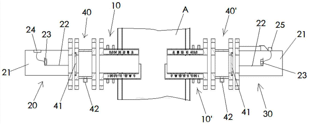
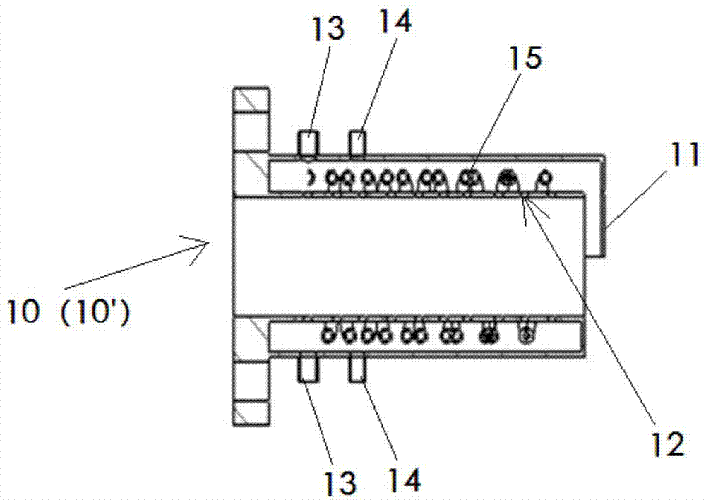
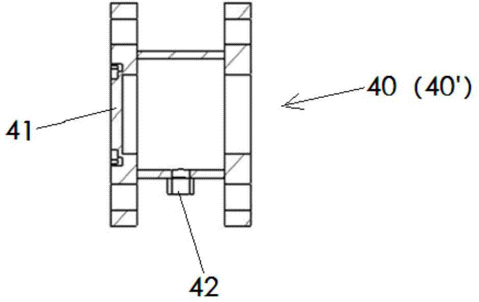
[0009] The present invention will be further described below through specific implementation methods. The flue gas temperature in different flue A varies greatly. For the flue gas with lower temperature, the main purpose is to prevent dust from affecting the laser projection. Therefore, the scheme that the present invention takes is as figure 1 As shown, a device for detecting smoke in the flue, which includes the first and second pipe bodies 10 and 10' respectively arranged on the side walls of the flue A corresponding to both sides, the first and second pipe bodies 10, 10' are arranged along the same beam path, which crosses the flow path of the flue gas in the flue A, and the first and second pipes 10, 10' are arranged on the periphery of the flue A respectively. A light-transmitting sheet 41 that separates the inner cavity of the first and second tube bodies 10, 10' from the external environment. The outer sides of the two light-transmitting sheets 41 are respectively prov...


PUM


Abstract

The invention discloses a device for detecting flue gas in a flue. The device comprises a first pipe body and a second pipe body, which are arranged on two opposite side walls of the flue (A) and are sequentially arranged along a same light beam path; the light beam path is crossed with a flowing path of the flue gas in the flue (A); light transmission sheets, which are used for separating inner cavities of the first pipe body and the second pipe body from an external environment, are arranged at the parts, positioned at the periphery of the flue (A), of the first pipe body and the second pipe body; a laser transmitting assembly and a laser receiving assembly are arranged outside the two light transmission sheets, respectively; gas nozzles, which are used for spraying gas curtains to prevent dust in the flue gas from entering the pipe cavities of the first pipe body and the second pipe body, are arranged at pipe end orifices, extending into the flue (A), of the first pipe body and the second pipe body, respectively; the flowing direction of gas sprayed from the gas nozzles is crossed with the axial directions of the first pipe body and the second pipe body. According to the scheme, manual sampling and complicated sampling gas pretreatment are not needed, so that the detection speed is high, the measurement lag is avoided, and the measurement accuracy is high.

Description

technical field [0001] The invention relates to the field of detection of flue gas components in a copper smelting flue, in particular to a device for detecting flue gas in the flue. Background technique [0002] By detecting the flue gas composition in the flue, it can be judged whether each stage of copper smelting has reached the end. The current detection method for the flue gas in the flue is: the operator inserts the flue gas sampling pipe into the flue, starts the gas sampling pump to extract and sample, and then filters, heats, and condenses the extracted gas (or pipeline heating) After pretreatment, it enters the host of the gas tester to detect the composition of the gas. The operation process of gas sampling and pretreatment in this scheme is complicated, and due to the error of gas sampling and the problem of measurement time lag, the deviation of measurement results is relatively large. Contents of the invention [0003] In order to solve the above problems,...

Claims


Application Information

Patent Timeline
IPC IPC(8): G01N21/17
Inventor 吴华峰张玉钧高闽光何莹徐金凤刘建国尤坤蔡永厚宋修明黄永峰
Owner HEFEI GOLD STAR MECHATRONICS TECH DEV CO LTD
Learn More