A Coupling Capacitive Voltage Divider with Potential Gradient Shield

A potential gradient, coupling capacitor technology, applied in the direction of voltage divider, can solve the problems of increasing manufacturing cost, process and test difficulty, unfavorable field strength of coupling capacitor voltage divider unit components, etc., to improve safety and reliability. , Improve the ability to withstand transient processes, reduce the effect of capacitance

Active Publication Date: 2016-09-21
STATE GRID CORP OF CHINA +1
View PDF10 Cites 0 Cited by
  • Summary
  • Abstract
  • Description
  • Claims
  • Application Information

AI Technical Summary

Problems solved by technology

In the past, in order to reduce the interference effect of the external electric field on the CVT error characteristics, the method of increasing the capacitance of the coupling capacitor was often used, which not only increased the manufacturing cost of the equipment, the difficulty of the process and the test, but also adversely affected the field strength of the coupling capacitor voltage divider unit element. design

Method used


Image

  • A Coupling Capacitive Voltage Divider with Potential Gradient Shield
  • A Coupling Capacitive Voltage Divider with Potential Gradient Shield
  • A Coupling Capacitive Voltage Divider with Potential Gradient Shield

Examples


Embodiment 1

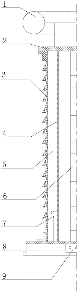
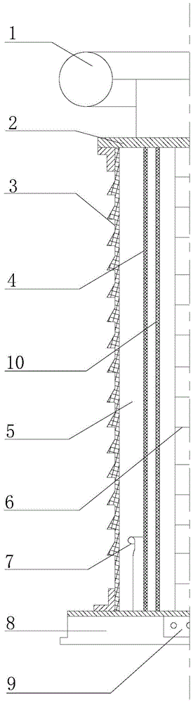
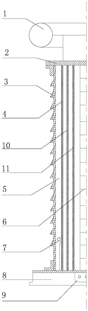
[0048] The present invention provides that the present invention provides a kind of coupling capacitive voltage divider with potential gradient shielding, as Figure 4-Figure 9 , the voltage divider includes a high-voltage end shielding ring 1, an upper flange 2, a body, a base 8 and a junction box 9; the high-voltage end shielding ring 1 is located at the top of the body, and is connected to the body Connection; the bottom of the body is fixed on the base 8, and the junction box 9 is arranged on the base 8.

[0049] The body includes a casing 3, a body body 6, a potential gradient shielding cylinder 4 and a low-voltage end shielding ring 7; the potential gradient shielding cylinder 4, the low-voltage end shielding ring 7 and the casing 3 are sequentially arranged from the inside to the outside On the outside of the body 6 , the shielding cylinder 4 with potential gradient is parallel to the shielding ring 7 at the low-voltage end, and is arranged perpendicular to the base 8 ....


PUM


Abstract

The invention provides a coupling capacitor voltage divider with potential gradient shielding, which includes a high-voltage end shielding ring, an upper flange, a device body, a base, and a junction box; the high-voltage end shielding ring is located on the top of the device body, and is The blue is connected with the body; the bottom of the body is fixed on the base, and the junction box is arranged on the base. On the basis of reducing the capacitance of the coupling capacitor voltage divider and ensuring that the voltage division ratio of the voltage divider is not affected by external objects and changes in the electric field, the invention provides a coupling capacitor voltage divider with potential gradient shielding, which can be used as a coupling Capacitors are used in EVT to improve the ability of the EVT secondary system to withstand transient processes; they can also be used as post insulators with a voltage divider function, used for monitoring substation voltages and measuring grid transient overvoltages, used in substations and Primary voltage monitoring for line system debugging; it can also be used in low-power CVT with higher insulation performance.

Description

technical field [0001] The invention relates to a voltage divider, in particular to a coupling capacitor voltage divider with potential gradient shielding. Background technique [0002] The grounding resistance of the substation and the residual inductance of the grounding network are much larger than the grounding impedance of the high-voltage laboratory with excellent performance, and even the difference is one to two orders of magnitude. When a transient overvoltage occurs in the power grid, the pulse current passing through the capacitive equipment will cause the potential of the ground terminal of the capacitive equipment to rise instantaneously. Great harm. [0003] One feature of the smart grid is to move the background secondary equipment that was far away from the primary equipment to the vicinity of the primary equipment, including a large number of state monitoring devices to realize the intelligence of transformers, switches, combined electrical appliances (GIS)...

Claims


Application Information

Patent Timeline
Patent Type & Authority Patents(China)
IPC IPC(8): G01R15/06
Inventor 王欢王晓琪项琼汪泉吴士普汪本进余春雨李璿毛安澜杜研冯宇
Owner STATE GRID CORP OF CHINA
Why Eureka
Try Eureka