
Shielding cover structure

A technology of shielding cover and polyimide layer, which is applied in the fields of magnetic field/electric field shielding, electrical components, flexible containers, etc. Effect

Active Publication Date: 2016-05-04
SHENZHEN SUNWAY COMM
View PDF7 Cites 0 Cited by
  • Summary
  • Abstract
  • Description
  • Claims
  • Application Information

AI Technical Summary

Problems solved by technology

Although this solution can solve the problem that the cover is easy to realize when disassembling and assembling, it still has the above-mentioned other disadvantages

Method used


Image

  • Shielding cover structure
  • Shielding cover structure
  • Shielding cover structure

Examples


Embodiment 1

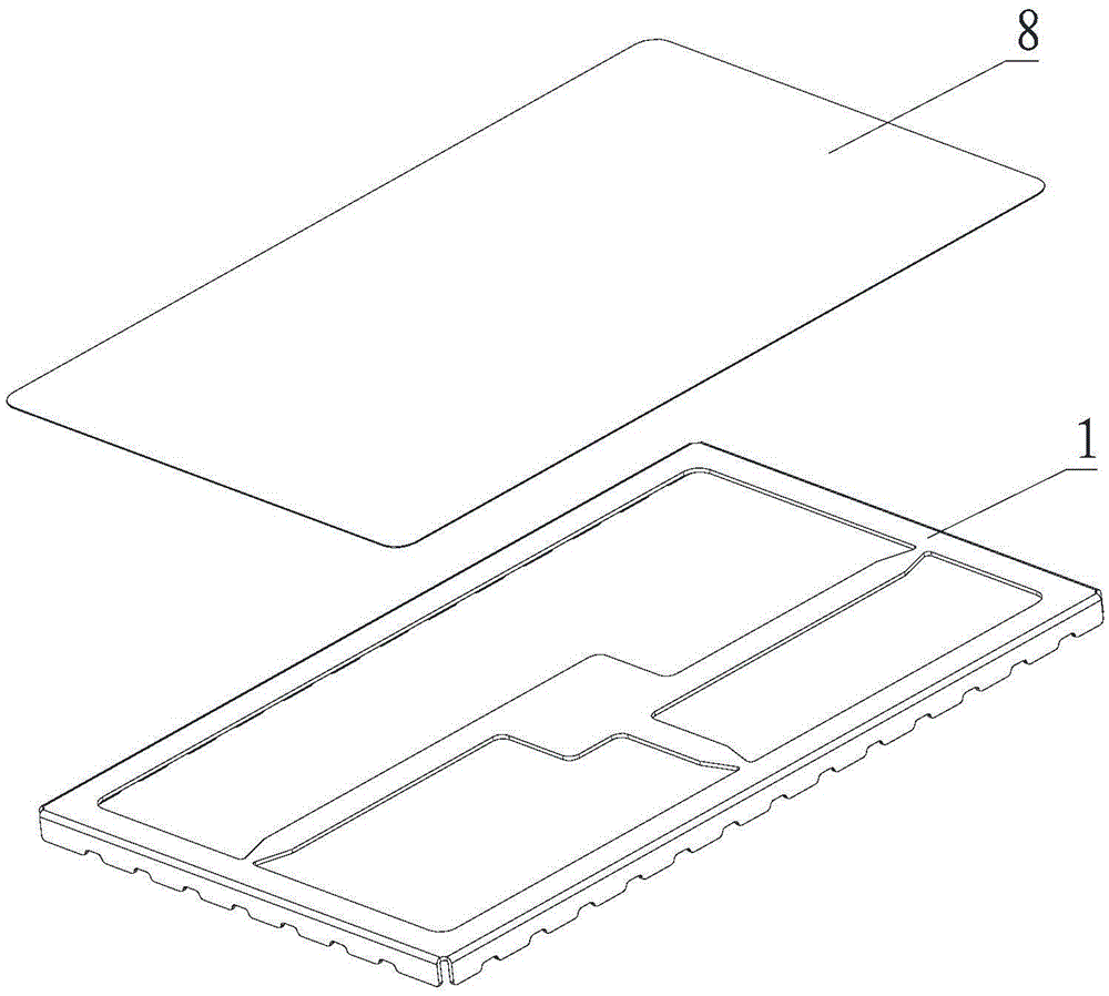
[0042] Please refer to image 3 , Embodiment 1 of the present invention is: a shielding cover structure, which can be applied to the electromagnetic shielding of electrical equipment and chips on circuit boards. The above-mentioned shielding cover frame 1 is bonded, and when the shielding cover is set on the chip, a closed cavity can be formed, thereby playing the function of shielding. The overall structure is as follows Figure 4 shown.

[0043] Such as Figure 5 As shown, the FPC8 includes a first polyimide layer 81, a first adhesive layer 82 and a metal layer 83, and one side of the metal layer 83 is connected to the first polyimide layer through the first adhesive layer 82. The imine layer 81 is bonded. Preferably, the area of ​​the metal layer 83 is more than 60% of the area of ​​the first polyimide layer 81 to ensure the shielding effect. In this embodiment, one side of the metal layer 83 is used as an adhesive surface to be bonded to the shielding case frame 1 . P...

Embodiment 2

[0051] Please refer to Figure 8 , Embodiment 2 of the present invention is an improvement of Embodiment 1, and the similarities will not be repeated here.

[0052] The FPC8 also includes a second polyimide layer 84 and a second adhesive layer 85, and the other side of the metal layer 83 is bonded to the second polyimide layer 84 through the second adhesive layer 85. catch. Optionally, the area of ​​the second polyimide layer 84 is the same as that of the first polyimide layer 81 .

[0053] Optionally, the FPC 8 further includes a second insulating layer 87 covering the second polyimide layer 84 . Optionally, the area of ​​the second insulating layer 87 is the same as that of the first insulating layer 86 .

[0054]In this embodiment, polyimide is also provided on the other side of the metal layer, which further protects the metal layer, makes the metal layer difficult to be corroded or damaged, and ensures the shielding effect.

[0055] In summary, in the shielding cover ...


PUM


Abstract

The invention discloses a shielding cover structure. The shielding cover structure comprises a shielding cover rack and also comprises a flexible printed circuit (FPC), wherein the FPC is bonded with the shielding cover rack by a conductive adhesive layer. With the adoption of the FPC as a shielding cover, metal wiring inside the FPC can achieve a shielding effect, an insulation effect can be achieved by an insulation layer of the shielding cover structure, and the weight of the shielding cover can be greatly reduced; moreover, the FPC is relatively small in volume, the space of other components cannot be compressed; the FPC and the shielding cover rack are bonded by the conducive adhesive layer, the fabrication process is simple, the requirement for a fabrication device is reduced, and the fabrication cost is saved; meanwhile, the FPC is made of a flexible material, the shielding of a space curved-surface product can be achieved; and moreover, heat can be effectively dissipated, the temperature of the whole machine is reduced, and a favorable environment is provided for the running of the whole machine.

Description

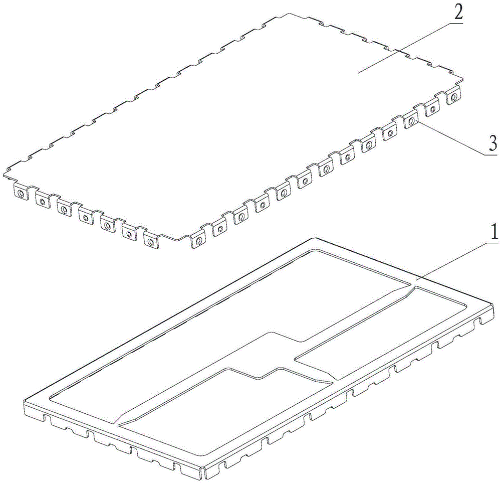
technical field [0001] The invention relates to the field of shielding equipment, in particular to a shielding cover structure. Background technique [0002] The current solution is the combination of the shield bracket and the shield cover, such as figure 1 As shown, the shielding case frame 1 and the shielding case cover 2 are both completed by metal stamping, and the convex shell 3 is punched out on the shielding case frame or the shielding case cover, and fastened to another piece. But this solution has the following disadvantages: [0003] a. The shielding cover needs to be punched, and the material needs a certain thickness to ensure its strength; [0004] b. Stamping dies and machines have high requirements, product flatness control is difficult, and the defective rate is high; [0005] c. Repeated disassembly and assembly after assembly is likely to cause deformation of the cover, etc., which may cause problems such as reduced shielding effect, fall off of the cov...

Claims


Application Information

Patent Timeline
Patent Type & Authority Applications(China)
IPC IPC(8): H05K9/00
CPCH05K9/0007H05K9/0043
Inventor 张海军
Owner SHENZHEN SUNWAY COMM
Learn More