Electromagnetic wave generating device

A technology for generating devices and electromagnetic waves, which is applied in the electromagnetic field and can solve problems such as electron dispersion

Inactive Publication Date: 2014-02-12
陆振民
View PDF7 Cites 2 Cited by
  • Summary
  • Abstract
  • Description
  • Claims
  • Application Information

AI Technical Summary

Problems solved by technology

[0003] The purpose of the present invention is to provide an electromagnetic wave generating device that makes electrons more concentrated during operation, so as to solve the problem that electrons are relatively dispersed during travel in the prior art

Method used


Image

  • Electromagnetic wave generating device
  • Electromagnetic wave generating device
  • Electromagnetic wave generating device

Examples


Embodiment Construction

[0020] The present invention will be described in further detail below through specific implementation examples and in conjunction with the accompanying drawings.

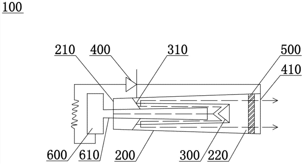
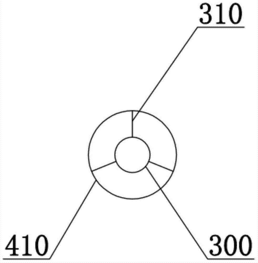
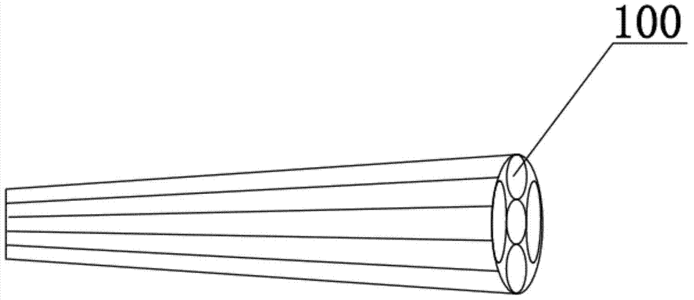
[0021] see Figure 1-Figure 5 , the dotted line in the figure is the path of the electrons. In an embodiment of the present invention, an electromagnetic wave generating device 100 is provided, including an electron generating part 600 that generates electrons; an incident part 200 that injects electrons into the electron generating part; a guide part that changes the velocity of incident electrons; The deflection part 300 intercepts the incident electrons and changes the traveling direction of the incident electrons, and the end of the guide part away from the electron generating part is the anode end 410 . The electron generator 600 can also be replaced by a snapping sound generator. The incident part 200 is a part into which electrons enter after being emitted from the electron generating part 600 and leaving....


PUM


Abstract

The invention discloses an electromagnetic wave generating device which comprises an electron generating part, an incoming part, a direction changing part and a guiding part. The electron generating part is used for generating electrons, the electrons generated by the electron generating part come in the incoming part, the direction changing part for intercepting the incoming electrons and changing the proceeding directions of the incoming electrons is arranged inside the incoming part, the guiding part is used for changing the speeds and the proceeding directions of the incoming electrons, and one end, far away from the electron generating part, of the guiding part is an anode end. According to the electromagnetic wave generating device, as the directions of the electrons are changed for multiple times inside the incoming part, the electrons can be gathered in the process that the electrons proceed inside the incoming part, the electrons can be gathered into an area in a relative concentration mode after leaving the incoming part, and therefore the number of the electrons received inside a unit area of a region is increased.

Description

technical field [0001] The present invention relates to the electromagnetic field, in particular to an electromagnetic wave generating device and a multi-unit electromagnetic wave generator using the electromagnetic wave generating device. Background technique [0002] At present, the commonly used electromagnetic wave emitting devices simply emit electrons through the emission source. Because the electrons emitted by the emission source propagate outward in the form of scattering, as the propagation distance increases, the electrons are more dispersed during the traveling process, which will cause the electrons to finally fall into a relatively wide area, and the electron receiving area unit A problem where the area receives a relatively small number of electrons. Contents of the invention [0003] The object of the present invention is to provide an electromagnetic wave generating device that makes electrons more concentrated during operation, so as to solve the problem...

Claims


Application Information

Patent Timeline
Patent Type & Authority Applications(China)
IPC IPC(8): H01J3/02H01J3/14
Inventor 陆振民陆子野
Owner 陆振民
Why Eureka
Try Eureka