A kind of transistor and transistor array
A technology of transistors and transistor units, applied in semiconductor devices, electric solid state devices, electrical components, etc., can solve the problems of impracticality, application, design and manufacturing difficulty
- Summary
- Abstract
- Description
- Claims
- Application Information
AI Technical Summary
Problems solved by technology
Method used
Image
Examples
Embodiment 1
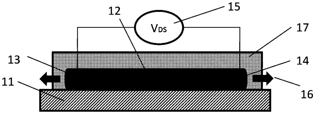
[0049] In this embodiment, the transistor is arranged on the substrate, the connection line between the first electrode and the second electrode is basically parallel to the substrate, and the piezoelectric body is a bulk material, see figure 2 , the transistor is disposed on the substrate 11, the substrate 11 includes a first electrode 13 of the transistor, a piezoelectric body 12 and a second electrode 14, the first electrode 13 and / or the second electrode 14 are used to apply strain to the piezoelectric body 12, Stress or pressure16. Wherein, the piezoelectric body 12 is a bulk material, which may be a bulk material with a wurtzite structure, a bulk material with a sphalerite structure, a bulk material with a lithium niobate structure, or a bulk material with semiconductor properties, such as ZnO, GaN, CdS, InN, InGaN, CdTe, CdSe or ZnSnO 3 and other materials. In this embodiment, the preparation method of the piezoelectric body is to selectively deposit the material of ...
Embodiment 2
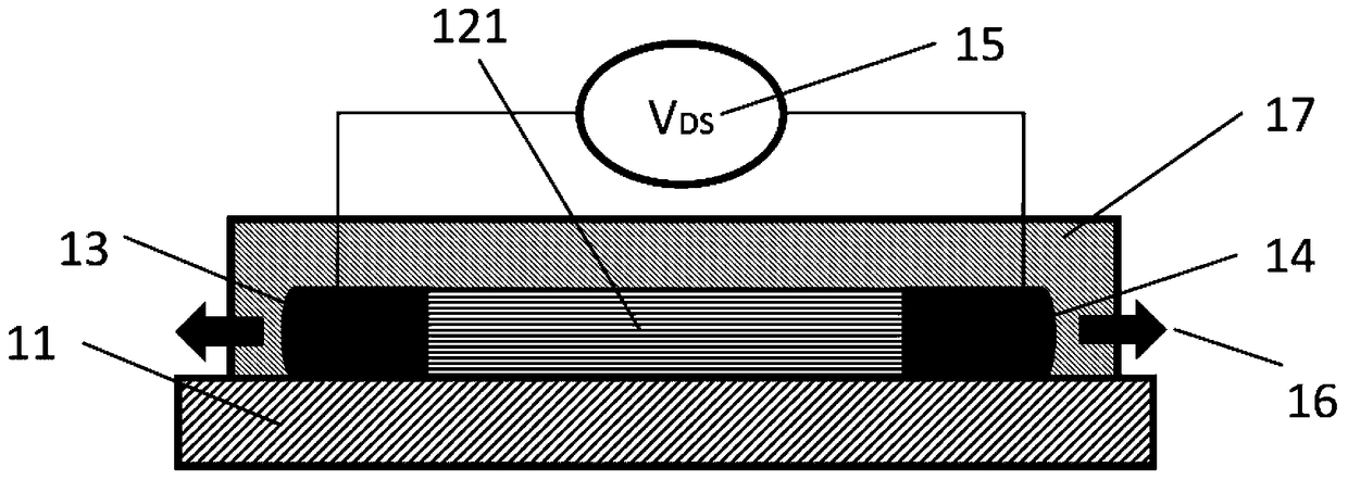
[0056] The difference between this embodiment and Embodiment 1 is that the piezoelectric body of the transistor is a one-dimensional piezoelectric structure, and the one-dimensional piezoelectric structure may include piezoelectric nanowires, nanowires, nanorods, nanocolumns or nanobelts. . In this embodiment, the number of one-dimensional piezoelectric structures is not limited, and it may be one one-dimensional piezoelectric structure, such as a nanowire or nanorod, or multiple one-dimensional piezoelectric structures arranged in parallel, such as multiple parallel arrayed nanowires or nanorods. see image 3 , the piezoelectric bodies 121 are nanowires or nanorods arranged in parallel, the first electrode 13 and the second electrode 14 are oppositely arranged at the two ends of the nanowire or nanorod, and the first electrode 13 and / or the second electrode 14 is used to apply strain or stress to the piezoelectric body; the material of the piezoelectric body 121 produces a ...
Embodiment 3
[0061] The difference between this embodiment and Embodiment 1 and Embodiment 2 is that the piezoelectric body of the transistor is a piezoelectric film, see Figure 4 , the piezoelectric body 122 is a piezoelectric film, and the piezoelectric body 122 shown in the figure is a piezoelectric film cross section. The first electrode 13 and the second electrode 14 are oppositely arranged at two ends of the piezoelectric film or piezoelectric nanoribbon.
[0062] The piezoelectric body 122 is a piezoelectric film, the connecting line of the first electrode 13 and the second electrode 14 is substantially parallel to the surface of the piezoelectric film, and the first electrode 13 and the second electrode 14 are connected to the two end faces of the piezoelectric film (That is, the piezoelectric film between the first electrode and the second electrode is a piezoelectric body 122 ), the size of the first electrode 13 and the second electrode 14 should be at least equivalent to the t...
PUM
 Abstract
Description
Claims
Application Information
 - R&D
- Intellectual Property
- Life Sciences
- Materials
- Tech Scout
- Unparalleled Data Quality
- Higher Quality Content
- 60% Fewer Hallucinations
Browse by: Latest US Patents, China's latest patents, Technical Efficacy Thesaurus, Application Domain, Technology Topic, Popular Technical Reports.
© 2025 PatSnap. All rights reserved.Legal|Privacy policy|Modern Slavery Act Transparency Statement|Sitemap|About US| Contact US: help@patsnap.com


