
Optical-mechanical scanning antenna device used for scanning imaging

A technology of scanning antenna and scanning imaging, applied in the direction of antenna, electrical components, etc., can solve the problems of high price, difficulty of electronic scanning devices, large loss of feeding system, etc.

Active Publication Date: 2014-02-12
CHANGZHOU INST OF TECH
View PDF3 Cites 13 Cited by
  • Summary
  • Abstract
  • Description
  • Claims
  • Application Information

AI Technical Summary

Problems solved by technology

It is usually used in the microwave low-frequency end where the device is cheap and the technology is simple. In the microwave high-frequency band and the terahertz wave low-frequency end, it is quite difficult and expensive to design an effective electronic scanning device, and the loss of the feeding system is large. Therefore, in the microwave high-frequency band , There are not many applications of terahertz waves in the low frequency band

Method used


Image

  • Optical-mechanical scanning antenna device used for scanning imaging
  • Optical-mechanical scanning antenna device used for scanning imaging
  • Optical-mechanical scanning antenna device used for scanning imaging

Examples


Embodiment Construction

[0026] The present invention will be described in detail below in conjunction with specific embodiments.

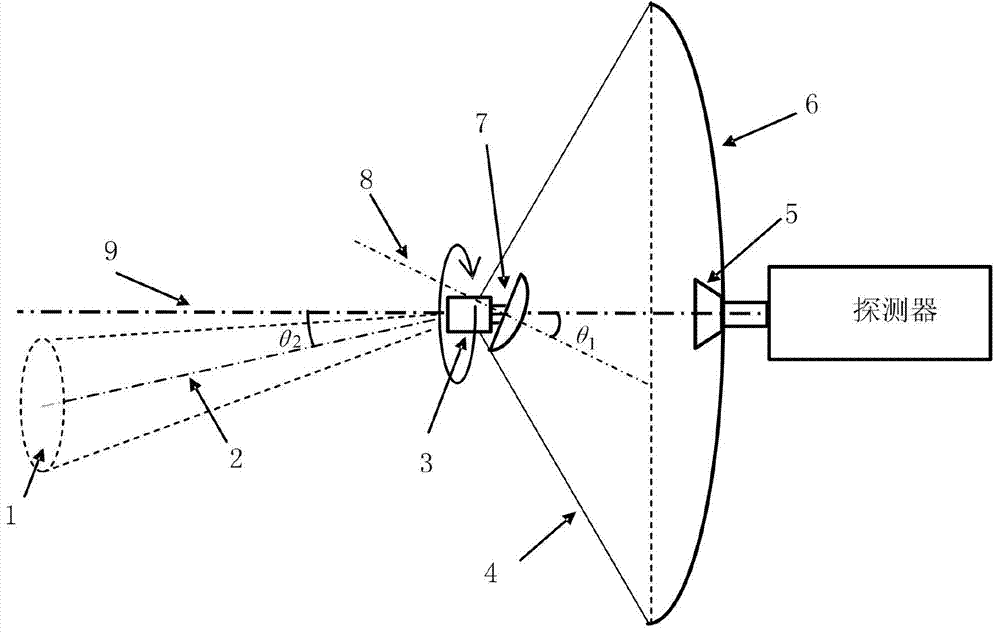
[0027] refer to figure 1 , an optical-mechanical scanning antenna device for scanning imaging applications, including a main reflector 6, a feed source 5, a secondary reflector 7, a spin motor 3, and a detector, the optical-mechanical scanning antenna device is a Cassegrain antenna structure, and the The main reflector 6 described above is a paraboloid; the feed source 5 is connected to the detector at the end of the feed source 5; the feed source 5 is connected to the main reflector 6 at the feed source 5 middle sections, the center of the main reflection surface 6; the central axis of the main reflection surface 6 coincides with the central axis of the feed source 5; the secondary reflection surface 7 is a paraboloid; the central axis of the secondary reflection surface 7 is aligned with the main reflection surface The central axis of the surface 6 is at a certain angl...


PUM


Abstract

The invention discloses an optical-mechanical scanning antenna device used for scanning imaging. The optical-mechanical scanning antenna device used for scanning imaging comprises a main reflecting surface (6), a feed source (5), an auxiliary reflecting surface (7), a spinning motor (3) and a detector, wherein a certain angle is formed between the central axis of the auxiliary reflecting surface (7) and the central axis of the main reflecting surface (6). According to the optical-mechanical scanning antenna device used for scanning imaging, due to the fact that the auxiliary reflecting surface of a Cassegrain antenna is inclined by a certain angle, antenna wave beams deviate from the central axis of the main reflecting surface by a certain angle; due to the fact that the inclined auxiliary reflecting surface spins around the central axis of the main reflecting surface of the antenna, circular scanning is achieved through spinning of the antenna wave beams which deviate from the central axis of the main reflecting surface by the certain angle.

Description

technical field [0001] The invention relates to an optical-mechanical scanning antenna device for scanning imaging application. Background technique [0002] Scanning imaging technologies, such as microwave imaging (including millimeter wave and submillimeter wave imaging) and terahertz wave imaging, can be widely used in industrial inspection, military reconnaissance, guidance and tracking, medical imaging, remote sensing detection, human body security inspection and other fields. Especially because microwaves and terahertz waves have good penetration and high spatial resolution, they can detect concealed prohibited items (guns, knives, explosives, etc.) through human clothing, and have important applications in technical fields such as anti-terrorism and aviation security inspections. . [0003] In recent years, due to the development of device and instrument technology, microwave and terahertz wave imaging technology has continued to develop, and the following systems ha...

Claims


Application Information

Patent Timeline
IPC IPC(8): H01Q3/08H01Q19/19
Inventor 时翔殷娟季芳王东亚
Owner CHANGZHOU INST OF TECH
Learn More