
Socket connector

A socket connector, contact pad technology, applied in the direction of connection, connecting device parts, electrical components, etc., can solve the problems of intrusion interference, long conductive path, unstable potential, etc., and achieve the effect of reliable electromagnetic shielding

Inactive Publication Date: 2014-02-12
SMK CO LTD
View PDF5 Cites 2 Cited by
  • Summary
  • Abstract
  • Description
  • Claims
  • Application Information

AI Technical Summary

Problems solved by technology

[0009] According to this conventional receptacle connector 100, there is the following problem: Since the periphery of the contact 103 through which the high-frequency signal flows is surrounded by the shield shell metal part 104 set to the ground potential, it is electromagnetically shielded, but passes through the opposite side of the connection. In such a way that the pin is not easy to pull out, the cylindrical shielding shell metal part 104 is provided with a matching hole for matching with the opposite side pin and a matching protrusion cut and erected from a part of the shielding shell metal part 104, and these matching parts are formed, so that the shielding Openings are formed in a part of the shell metal fittings 104, and the fitting recess 105 is opened in a state where the opposite side plug is not connected, and through these openings, noise enters from the outside or a high-frequency signal generated to flow through the contacts 103 is exposed to the outside. of unwanted radiation
[0010] In addition, on the above-mentioned receptacle connector 100, a reinforcing metal part 101 is installed to protect the protruding plate part 102 and the contact 103 from the wrongly inserted opposite side pin, and to apply external force to the leg part 103a of the other contact 103. The leg portion 101b is fixed to the printed circuit board, but the metal plate is used mainly to act on the mechanical external force, and it is not electrically connected to any of them, and becomes an unstable potential
Since the reinforcing metal parts 101 of this unstable potential are arranged close to the contacts 103, the characteristic impedance of the high-frequency transmission line flowing through the contacts 103 becomes unstable and the transmission efficiency deteriorates.
[0011] If the leg portion 101b of the reinforcing metal part 101 is soldered to the ground pattern that is the ground potential, the characteristic impedance can be stabilized by using the reinforcing metal part 101 as the ground potential, but it is necessary to form the leg part on the reinforcing metal part 101 101b, and it is necessary to dispose the ground pattern at a position different from the connection position of the shielding case metal part 104, thereby causing a new problem of lowering the mounting density of the printed circuit board
[0012] In addition, when the shielding case metal part 104 and the reinforcement metal part 101 are connected through the ground pattern on the printed circuit board, the conductive path connecting the two becomes long, and a potential difference may occur due to high-frequency disturbance flow, which may not be sufficiently obtained. shielding effect

Method used


Image

  • Socket connector
  • Socket connector
  • Socket connector

Examples


Embodiment Construction

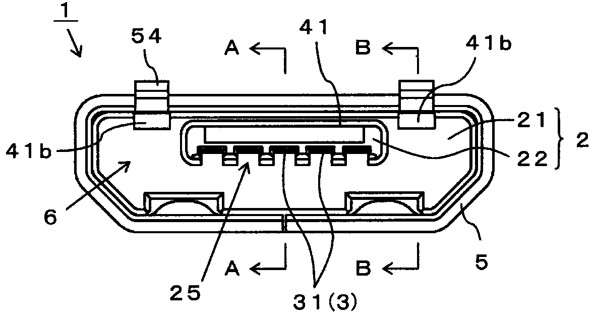
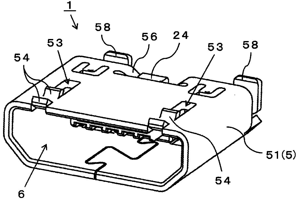
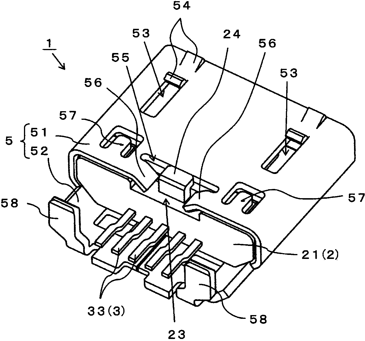
[0053] Hereinafter, for the receptacle connector 1 of one embodiment of the present invention, Figure 1 to Figure 11 Describe in detail. Socket connector 1 is used with the slave figure 1 The plug on the opposite side, which is not shown in the figure, is inserted into the front side as shown. In the following, in the description of each part of the receptacle connector 1, the connection direction with the plug on the opposite side is taken as the front. Figure 4 In the plan view of the plug connector 1 viewed from above, the lower part is referred to as the front, the upper part is referred to as the rear, and the left-right direction is referred to as the left-right direction.

[0054] As shown in these figures, the receptacle connector 1 includes: an insulating case 2; a plurality of contacts 3 and reinforcing metal parts 4 integrally installed on the insulating case 2; Shielding shell metal parts 5. The insulating case 2 uses an insulating synthetic resin such as a l...


PUM


Abstract

The invention provides a socket connector which utilizes a reinforced metal component for protecting a contact with outside forces and can reliably and electromagnetically shield the flowing contact of high-frequency signals. On the reinforced metal component with a reinforcing cover covering one part of the surface of a protruding plate part, a contact pad exposed out of one part of the outer periphery of a housing main body is integrally formed, and is contacted with a shielding housing metal component along the outer periphery of housing main body.

Description

technical field [0001] The present invention relates to a receptacle connector, wherein the periphery of the protruding plate part where a plurality of contacts are exposed is covered by a cylindrical shielding shell metal part, and the opposite side pin is fitted and connected to the fitting recess between the protruding plate part and the shielding shell metal part , in more detail, relates to a receptacle connector that electromagnetically shields a plurality of contacts with a ground-connected shield shell metal part. Background technique [0002] A receptacle connector for high-speed signal transmission such as a USB connector used in the USB (Universal Serial Bus) standard for connecting a host device and a peripheral device, and the surrounding of the projecting plate part where the contact is exposed is covered with a cylindrical shielding shell metal Parts are covered to block the contacts through which high-frequency signals flow from the outside. [0003] The plu...

Claims


Application Information

Patent Timeline
Patent Type & Authority Applications(China)
IPC IPC(8): H01R13/502H01R13/6591
Inventor 小野直之金泽和明
Owner SMK CO LTD
Learn More