socket connector

A socket connector and through-hole technology, which is applied in the field of socket connectors, can solve the problems of potential difference, high-frequency signal leakage, complex mold structure, etc., and achieve the effects of increased grounding connection positions, reliable electromagnetic shielding, and reliable electrical connection

Inactive Publication Date: 2016-08-10
SMK CO LTD
View PDF4 Cites 0 Cited by
  • Summary
  • Abstract
  • Description
  • Claims
  • Application Information

AI Technical Summary

Problems solved by technology

[0011] In the conventional receptacle connector 100, a conductive metal plate is press-molded, and a shield piece 101c is formed at the rear end of the fitting cylindrical portion 101a to prevent the fitting cylindrical portion 101a from coming off forward with respect to the housing main body 102a. As for the pressing piece 101d, the shielding piece 101c cannot be made into a shape that covers the whole of the legs 103b of the plurality of contacts 103 and their welding parts, and sufficient shielding effect cannot be obtained only with the inverted T-shaped shielding piece 101c.
[0012] In addition, a pair of grounding legs 101b are cut out from the fitting cylinder 101a, or a mating hole 101e for mating with the mating side plug is formed so that the mating side plug inserted into the fitting barrel 101a cannot be easily pulled out. A part of the barrel portion 101a produces openings, and through these openings, there is a problem of generating unnecessary radiation that interferes with intrusion from the outside or leaks to the outside of a high-frequency signal transmitted in the contacts 103.
[0013] In addition, in the receptacle connector 100 in which the insulating housing 102 is assembled in the fitting cylindrical portion 101a, there is a gap between them, and water droplets or dust may flow from the fitting cylindrical portion 101a and the housing main body when the mating side plug is not inserted. The clearance of 102a enters the device where the receptacle connector 100 is installed
Therefore, it is known that when forming the insulating case, the metal part of the shielding case is insert-molded, and the outer peripheral surface and the rear opening of the fitting cylinder are covered with the integrally formed insulating case to seal the receptacle connector in the fitting barrel. However, since the insulating case covers the periphery of the fitting cylinder, the shielding case metal fittings are insert-molded so that the grounding leg for grounding the fitting cylinder and the shield piece around the leg covering the contact protrude from the insulating case. , the mold structure is complex
[0014] In addition, any one of the above-mentioned receptacle connector 100 and the receptacle connector with a waterproof structure is made of a conductive metal plate to form the fitting cylinder part and the shielding sheet. Therefore, on the ground pattern of the substrate, from the ground leg to each part The longer the distance, the higher the potential difference due to the flow of high-frequency noise, and the shielding effect may not be sufficient

Method used


Image

  • socket connector
  • socket connector
  • socket connector

Examples


Embodiment Construction

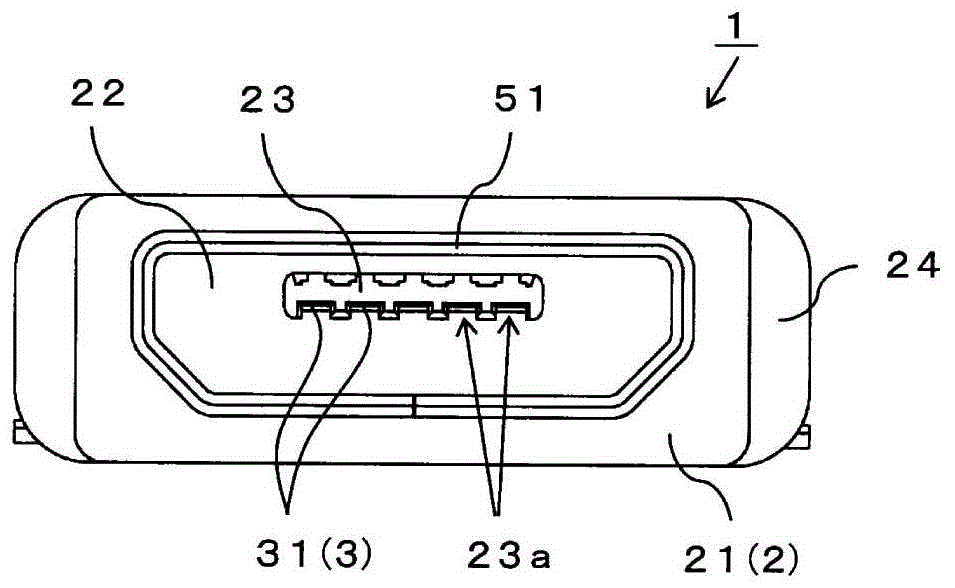
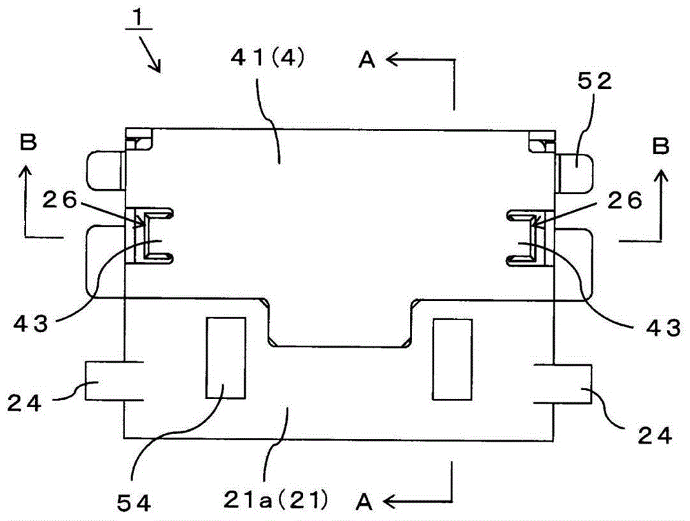
[0055] Below, use Figure 1 to Figure 9 A receptacle connector 1 according to one embodiment of the present invention will be described in detail. Socket connector 1 with slave figure 1 The unillustrated mating plug inserted in the front side shown is connected. In the following, the description of each part of the receptacle connector 1 takes the connection direction with the mating plug as the front. figure 2 In the plan view of , the lower part is referred to as the front, the upper part is referred to as the rear, and the left-right direction is referred to as the left-right direction.

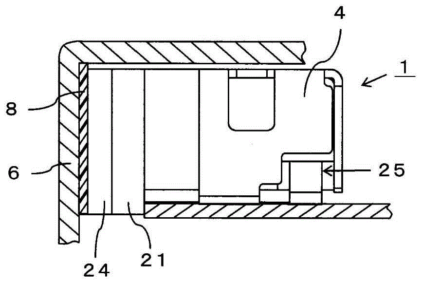
[0056] As shown in these figures, the receptacle connector 1 includes an insulating shell 2, a shielding shell metal part 5 integrally mounted on the insulating shell 2, and a plurality of contacts 3, and a plurality of contacts 3 installed along the rear plane and two sides of the insulating shell 2. Shield 4.

[0057] Such as Figure 6 As shown, the shielding case metal fitting 5 i...


PUM


Abstract

The present invention provides that the entirety of the legs of the contacts protruding rearward from the insulating case are covered with shield covers that are respectively grounded with the fitting cylinders around the contact parts surrounding the contacts, so as to reliably protect the contacts that transmit high-frequency signals. Receptacle connector with overall electromagnetic shielding. Through the insertion hole of the insulating case covering the outer peripheral surface of the fitting cylindrical part, a part of the fitting cylindrical part is an exposed part facing outward, and the exposed part is installed from the outside of the insulating case, and covers the whole of the leg part of the contact shield contact.

Description

technical field [0001] The present invention relates to a receptacle connector in which an insulating shell covers the outer peripheral surface of a fitting cylindrical portion of a shield metal fitting inserted into a counterpart side and an opening at the rear thereof, and more particularly relates to a shield covering from the insulating shell with a shield different from that of the shield shell metal fitting. Receptacle connector on the feet of the contacts protruding to the rear. Background technique [0002] A receptacle connector used for high-speed data transmission, such as a USB connector used in the USB (Universal Serial Bus) standard that connects the host device and peripheral devices, forms a fitting recess for inserting a suitable plug on the object side. The surface of the support plate portion of the insulating case of the inner coating of the concave portion is provided with a contact that is in contact with the plug-side contact of the mating plug. The m...

Claims


Application Information

Patent Timeline
Patent Type & Authority Patents(China)
IPC IPC(8): H01R13/52H01R13/6581
Inventor 小野直之高野龙太郎
Owner SMK CO LTD
Why Eureka
Try Eureka