

Rotating motors and electric power steering
A technology for rotating electrical machines and electric motors, applied in the direction of electric steering mechanisms, electromechanical devices, electric components, etc., can solve the problems of large volume and size of rotating electrical machines, and achieve reduced size, reduced volume and/or size, and high-precision coaxial The effect of positioning
- Summary
- Abstract
- Description
- Claims
- Application Information
AI Technical Summary
Problems solved by technology
Method used
Image

Examples
no. 1 approach )
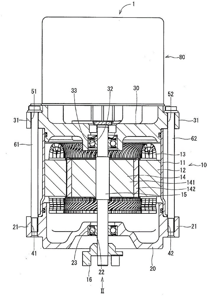
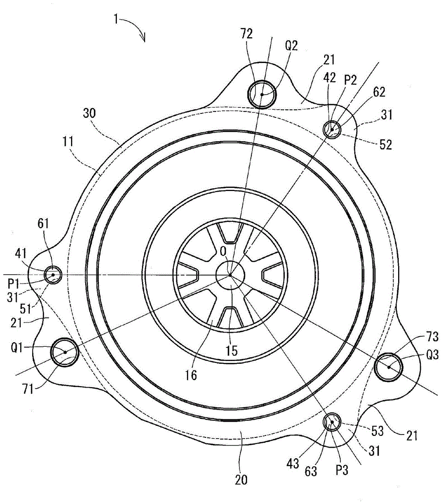
[0023] figure 1 and figure 2 A first embodiment of the rotating electrical machine in the present disclosure is shown. The rotary electric machine 1 is driven by receiving electric power supply and is used in, for example, an electric power steering apparatus to assist a steering operation of a vehicle.
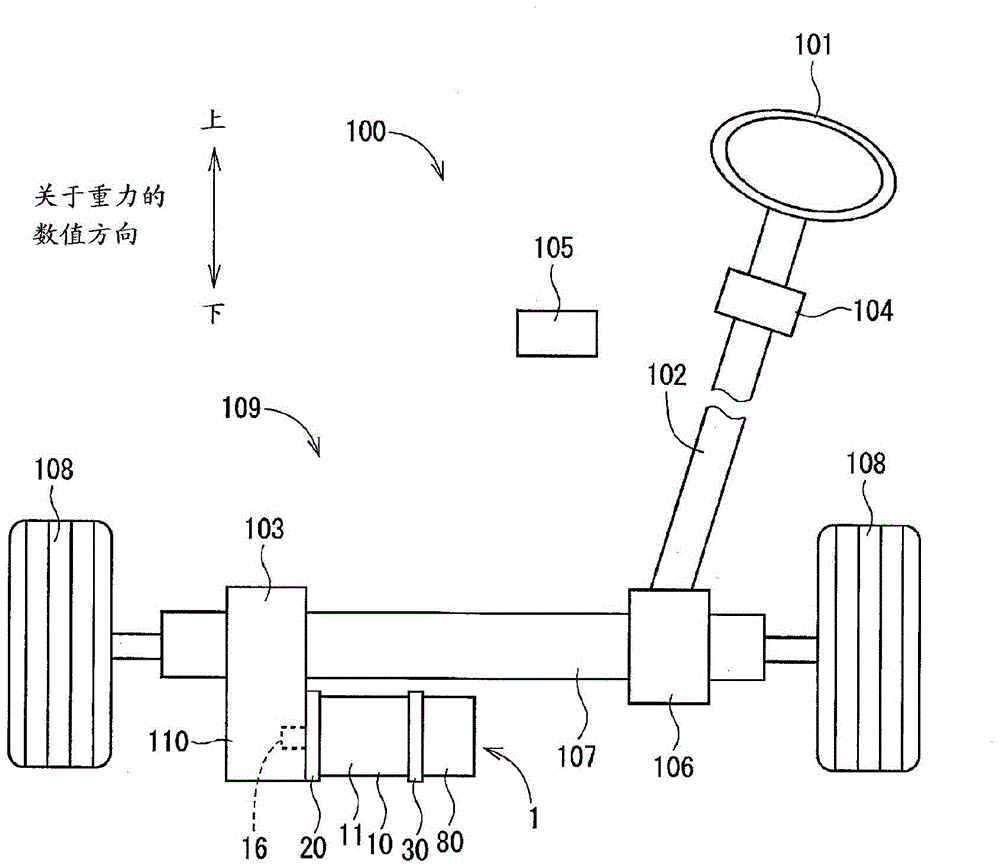
[0024] image 3 A system configuration of a steering system 100 having an electric power steering device 109 is shown. In an electric power steering device 109 , a torque sensor 104 is arranged on a steering shaft 102 and connected to a steering wheel 101 . The torque sensor 104 detects the steering torque input by the driver of the vehicle from the steering wheel 101 into the steering shaft 102 .
[0025] A pinion 106 is arranged on an end of the steering shaft 102 , and the pinion 106 is engaged with a rack shaft 107 . A pair of tires 108 are rotatably connected to both ends of the rack shaft 107 via tie rods or the like.
[0026] In this manner, when the driver of t...
no. 2 approach )
[0057] Figure 4 and Figure 5 A second embodiment of the rotating electric machine in the present disclosure is shown.
[0058] refer to Figure 4 , the output rod 17 is substantially cylindrical in shape and is arranged coaxially on the first end of the shaft 15 . A plurality of grooves extending in the axial direction are formed on the outer wall of the output rod 17 . The output rod 17 and the input portion (not shown) of the reduction gear 103 are connected by a belt. The belt transmits the rotation of the rotor 14 to the reduction gear 103 .
[0059] A first bottom cover hole 41 , a second bottom cover hole 42 , and a third bottom cover hole 43 are formed on the three bottom cover flanges 24 . More specifically, the first bottom cover hole 41 , the second bottom cover hole 42 , and the third bottom cover hole 43 are formed at equidistant positions (ie, equiangular intervals) around the circumference of the bottom cover 20 with respect to the axial center O. The axi...
no. 3 approach )
[0070] Figure 6 , Figure 7 ,as well as Figure 8 A third embodiment of the rotating electrical machine in the present disclosure is shown.
[0071] Such as Figures 6 to 8 As shown in , in this embodiment, a second bottom cover flange 26 and a first bottom cover flange 25 having a triangular shape are provided. The second bottom cover flange 26 is symmetrical and positioned along the centerline of the bottom cover 20 and on the outer periphery of the bottom cover 20 . In other words, each second bottom cover flange 26 is opposite the other second bottom cover flange 26 along the centerline (ie, located approximately 180° from each other). Accordingly, the first bottom cover flange 25 and the second bottom cover flange 26 are positioned at unequal angular intervals around the circumference of the bottom cover 20 .
[0072] The first bottom cover hole 41 is formed on the first bottom cover flange 25 . The second bottom cover hole 42 is formed on one of the second bottom ...
PUM
 Abstract
Description
Claims
Application Information