Resonator device, electronic device, electronic apparatus, and mobile object

A technology of vibration devices and electronic devices, which is applied in power oscillators, electrical components, impedance networks, etc., and can solve problems such as changes in vibration characteristics

Inactive Publication Date: 2014-02-12
SEIKO EPSON CORP
View PDF5 Cites 9 Cited by
  • Summary
  • Abstract
  • Description
  • Claims
  • Application Information

AI Technical Summary

Problems solved by technology

In the above-mentioned quartz oscillator, there is a problem that since the mounting terminal fixed to the mounting substrate and the both end supports of the vibrating piece are provided on the long sides of the base, the base is easily deformed due to an external force or a difference in thermal expansion coefficient. effect, and the stress applied to the vibrating piece causes the vibration characteristics to change

Method used


Image

  • Resonator device, electronic device, electronic apparatus, and mobile object
  • Resonator device, electronic device, electronic apparatus, and mobile object
  • Resonator device, electronic device, electronic apparatus, and mobile object

Examples


no. 2 Embodiment approach )

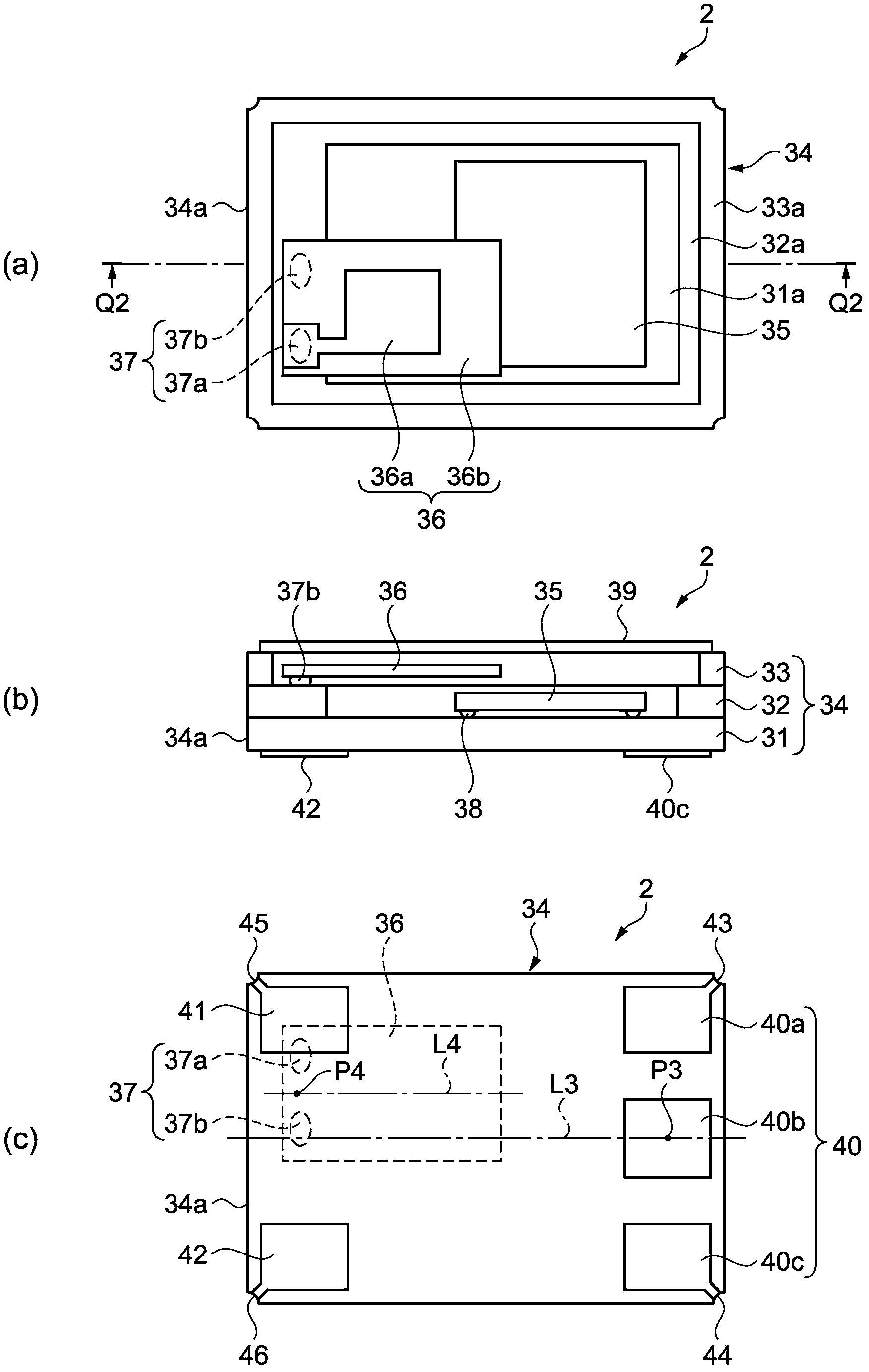
[0062] Next, use figure 2 A description will be given of a quartz oscillator as a resonator device according to the second embodiment of the present invention. figure 2 The outline of the quartz oscillator as the resonator device of the second embodiment is shown, in which (a) is a plan view, (b) is a Q2-Q2 cross-sectional view of (a), and (c) is a rear view of (a). In addition, in order to understand the description easily, figure 2 (A) shows the state after removing the cover. In addition, in the description of the second embodiment, the detailed description of the same configuration as that of the first embodiment described above may be omitted.

[0063] Such as figure 2 As shown, the quartz oscillator 2 as a vibrating device houses a vibrating element 36 and a semiconductor device (IC chip) 35 as an electronic component in the recess of the package 34, and seals the opening of the package 34 with a lid 39 to make the inside Keep it airtight.

[0064] [Vibration element]

[...


PUM


Abstract

A resonator device includes a base substrate having a fixation section to be attached to a mounting board and a free end, a resonator element having one end connected to a connection section located on the free end side of the base substrate, and a lid member adapted to airtightly seal the resonator element in a space between the lid member and the base substrate.

Description

Technical field [0001] The present invention relates to a vibration device, an electronic device, an electronic device and a mobile body using the vibration device. Background technique [0002] A quartz oscillator has been proposed as a vibrating device (for example, refer to Patent Document 1) in which a rectangular IC chip and a vibrating reed are mounted on a rectangular base (substrate). In the quartz oscillator described in Patent Document 1, the IC chip is mounted on the base by arranging the connection terminals on the long side of the IC chip and aligning the connection terminals with the short side of the base for connection. In addition, both ends of the vibrating piece are supported on both ends of the long side of the base, and mounting terminals of the base are also provided on both ends of the long side of the base. [0003] Patent Document 1: Japanese Patent Laid-Open No. 2002-176316 [0004] In the above-mentioned structure, when an external force is applied to the...

Claims


Application Information

Patent Timeline
Patent Type & Authority Applications(China)
IPC IPC(8): H03H9/02H03H9/19
CPCH03B1/00H03H1/00H03H9/0547H03H9/1021
Inventor 千叶诚一
Owner SEIKO EPSON CORP
Why Eureka
Try Eureka