Method and device for conducting interference measurement on interference measurement resources

An interference measurement resource and interference measurement technology, applied in the field of interference measurement on interference measurement resources

Active Publication Date: 2014-02-12
ZTE CORP
View PDF7 Cites 17 Cited by
  • Summary
  • Abstract
  • Description
  • Claims
  • Application Information

AI Technical Summary

Problems solved by technology

[0019] For the above-mentioned first and second rate matching resources, R11 and R10 have the same purpose of configuring zero-power CSI-RS, and the above-mentioned third rate matching resource is newly added by R11. In this way, a new zero-power CSI is required for R11 -RS configuration method, so that the zero-power CSI-RS of R11 includes at least two parts, one part is used for interference measurement, and the other part is used for rate matching, and the current R11 has no interference measurement scheme for zero-power CSI-RS for interference measurement

Method used


Image

  • Method and device for conducting interference measurement on interference measurement resources
  • Method and device for conducting interference measurement on interference measurement resources
  • Method and device for conducting interference measurement on interference measurement resources

Examples


Embodiment 1

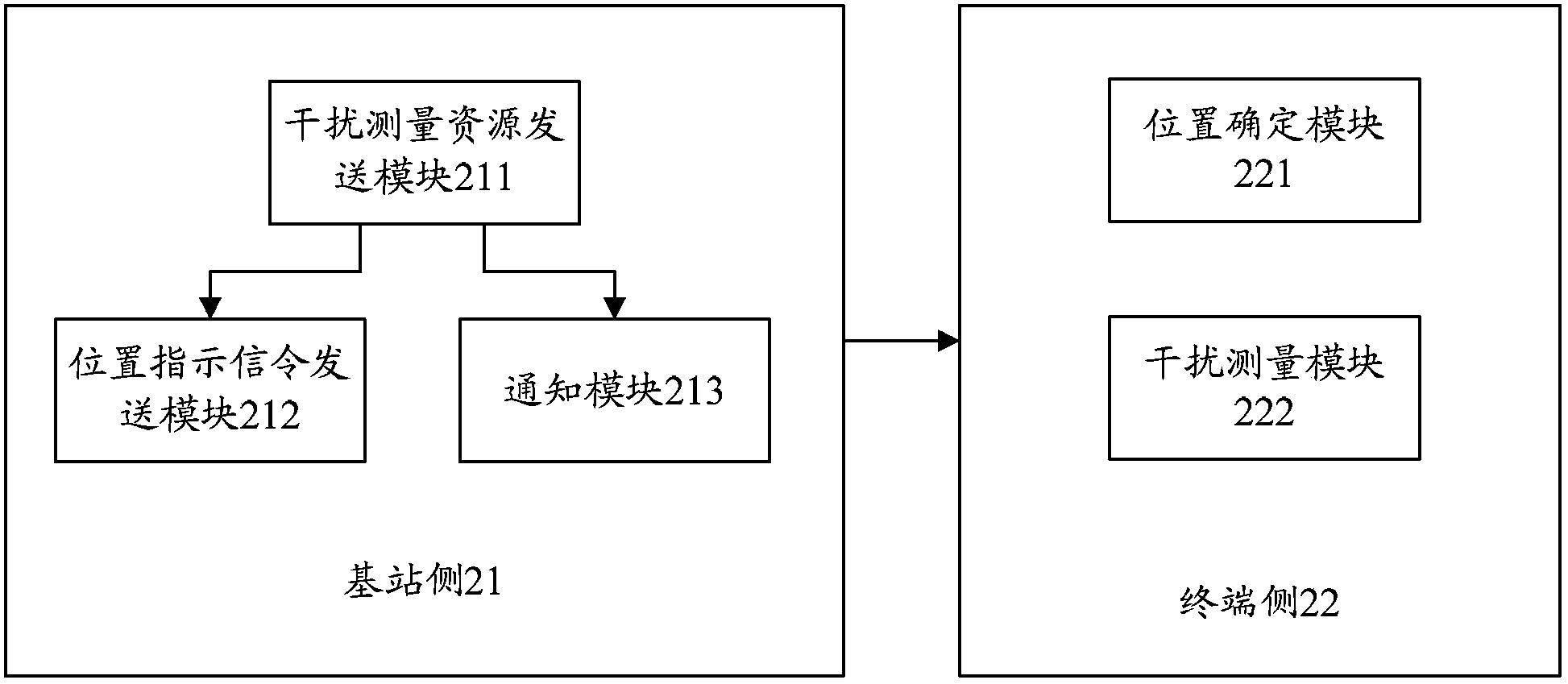
[0209] In this embodiment, assuming that UE1 is a user of R11 or higher version, the base station sends N sets of interference measurement resources on non-full bandwidth or full bandwidth, and sends the location indication signaling of each set of interference measurement resources to UE1; the location The indication signaling is terminal-specific high-level signaling, and the terminal-specific high-level signaling indicates the RB positions occupied by each set of interference measurement resources in a bit-mapped manner; or the terminal-specific high-level signaling uses resource allocation type 0, resource allocation type The resource allocation mode of 1 or resource allocation type 2 indicates the RB position occupied by each set of interference measurement resources in a corresponding subframe;

[0210] The UE1 determines the position of each set of interference measurement resources according to the terminal-specific high-level signaling, including subframe positions and...

Embodiment 2

[0212] In this embodiment, assuming that UE1 is a user of R11 or higher version, the base station sends N sets of interference measurement resources on non-full bandwidth or full bandwidth, and sends the location indication signaling of each set of interference measurement resources to UE1; the location The indication signaling is terminal-specific high-level signaling, and the terminal-specific high-level signaling indicates that the RB positions occupied by each interference measurement resource in a corresponding subframe are odd-numbered according to the preset interference measurement resource positions as odd-numbered RBs or even-numbered RBs RB or even RB;

[0213] The UE1 determines the position of the interference measurement resource according to the terminal-specific high-layer signaling, including the subframe position and the frequency domain position, and performs interference measurement on each interference measurement resource according to the non-full bandwidt...

Embodiment 3

[0215] In this embodiment, assuming that UE1 is a user of R11 or higher version, the base station sends N sets of interference measurement resources on non-full bandwidth or full bandwidth, and sends the location indication signaling of each set of interference measurement resources to UE1; the location The indication signaling is terminal-specific high-level signaling, and the terminal-specific high-level signaling indicates the subband positions occupied by each set of interference measurement resources in a bit-mapped manner; or the terminal-specific high-level signaling uses resource allocation type 0, resource allocation The resource allocation mode of type 1 or resource allocation type 2 indicates the subband position occupied by each set of interference measurement resources in a corresponding subframe;

[0216] The UE1 determines the position of each set of interference measurement resources according to the terminal-specific high-level signaling, including subframe pos...


PUM


Abstract

The invention discloses a method for conducting interference measurement on interference measurement resources. The method comprises the steps that a base station side sends N sets of interference measurement resources on non-full bandwidths or full bandwidths, and position indication signals of all the interference measurement resources are sent to a terminal side; the terminal side can determine the positions of the interference measurement resources according to the position indication signals of the interference measurement resources, and interference measurement is conducted on the interference measurement resources. The invention further discloses a device for conducting interference measurement on the interference measurement resources. According to the scheme, the time domain and frequency domain resource overheads and high-level signaling overheads are adopted as less as possible, and interference measurement is achieved on the different interference measurement resources.

Description

technical field [0001] The present invention relates to Long Term Evolution (LTE, Long Term Evolution) communication technology, and in particular to a method and equipment for performing interference measurement on interference measurement resources. Background technique [0002] After the Long Term Evolution (LTE, Long Term Evolution) system has gone through several versions of R8 / 9 / 10, the R11 technology has been accurately studied successively. At present, some R8 products are gradually commercialized, and R9 and R10 are subject to further product planning. [0003] After going through R8 and R9 stages, R10 added many new features on the basis of the first two, such as: Demodulation Reference Signal (DMRS, Demodulation Reference Signal), Channel State Information Reference Signal (CSI-RS, Channel State Information Reference Signal) and other pilot features, as well as transmission and feedback features such as 8-antenna support, etc., especially eICIC (ehanced Inter-Cel...

Claims


Application Information

Patent Timeline
Patent Type & Authority Applications(China)
IPC IPC(8): H04L5/00H04L1/00H04W72/04
CPCH04W24/08H04W24/10H04W72/04
Inventor 郭森宝张晨晨孙云锋陈东丽
Owner ZTE CORP
Why Eureka
Try Eureka