Downlink user dedicated demodulation reference signal transmitting method and device

A technology of demodulation reference signal and transmission method, which is applied in the field of transmission of downlink user-specific demodulation reference signal, can solve the problems of reducing NCT resource utilization, inability to transmit downlink data, DM-RS does not support transmission, etc., to improve transmission Efficiency and spectrum utilization, effect of improving data demodulation performance

Active Publication Date: 2014-02-12
DATANG MOBILE COMM EQUIP CO LTD
View PDF4 Cites 22 Cited by
  • Summary
  • Abstract
  • Description
  • Claims
  • Application Information

AI Technical Summary

Problems solved by technology

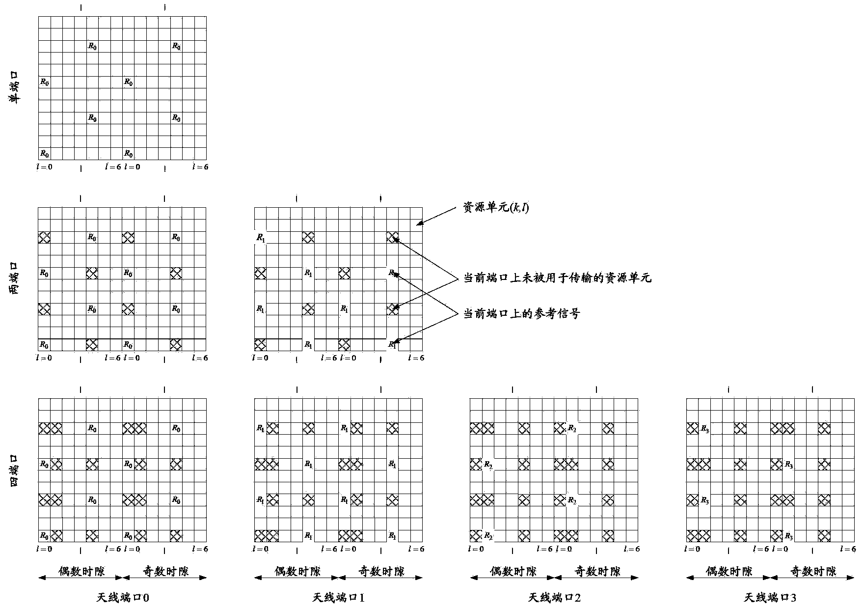
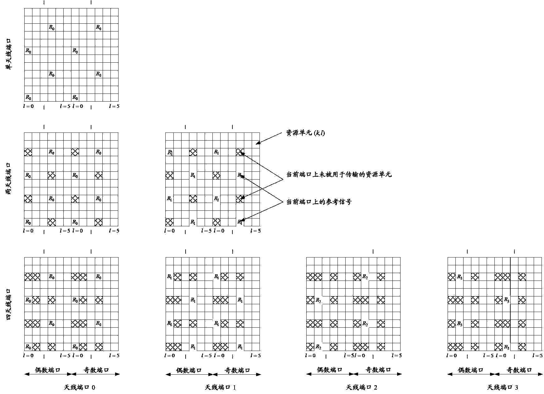
[0012] In summary, in the DM-RS resource mapping method defined in Rel-10, DM-RS is not transmitted on OFDM symbols in the control region, and E-PDCCH and PDSCH on NCT are mapped to all OFDM symbols in a subframe in the time domain During uplink transmission, the channel estimation information on at least the first N OFDM symbols needs to be obtained through the extrapolation algorithm of the finite column DM-RS, which reduces the data demodulation performance on the NCT; and the DM-RS does not support 3 DwPTS Transmission in special subframes of OFDM symbols, resulting in the inability to transmit downlink data based on DM-RS in special subframes containing only 3 OFDM symbols, reducing the resource utilization of NCT

Method used


Image

  • Downlink user dedicated demodulation reference signal transmitting method and device
  • Downlink user dedicated demodulation reference signal transmitting method and device
  • Downlink user dedicated demodulation reference signal transmitting method and device

Examples


Embodiment 1

[0139] Embodiment 1: Corresponding to the above method 1 or scheme 1 or mode 1;

[0140] For regular downlink subframes (that is, downlink subframes other than TDD special subframes), the DM-RS mapping resource in the DM-RS resource mapping method of the corresponding antenna port in Rel-10 is shifted in the time domain to obtain: Figure 6a to Figure 6j The shown DM-RS resource mapping method;

[0141] For example: Mode 1: Shift the first two columns of DM-RS mapping resources in Rel-10 to the 2nd and 3rd OFDM symbols (or the 3rd and 4th OFDM symbols), and get Figure 6a (under regular CP) and Figure 6b (under extended CP);

[0142] Method 2: Shift the last column of DM-RS mapping resources in Rel-10 to the second OFDM symbol (or the third OFDM symbol), and get Figure 6c (under regular CP) and Figure 6d (under extended CP);

[0143] Method 3: Shift the first two columns of DM-RS mapping resources in Rel-10 to the first and second OFDM symbols (or the second and third ...

Embodiment 2

[0153] Embodiment 2: Corresponding to the above method 1 or scheme 1 or mode 1;

[0154] For TDD special subframes, the DM-RS mapping resource in the DM-RS resource mapping method of the corresponding antenna port in Rel-10 is shifted in the time domain to obtain the following: Figure 7a to Figure 7i The DM-RS resource mapping method shown;

[0155] For example, for a conventional CP: Method 1: Shift the first two columns of DM-RS mapping resources in Rel-10 to the first and second OFDM symbols, and get Figure 7a ;

[0156] Method 2: Shift the first two columns of DM-RS mapping resources in Rel-10 to the first and second OFDM symbols, and for special subframe configurations 1 / 2 / 6 / 7, move the last two columns of DM-RS mapping resources to After shifting 2 OFDM symbols (or backward shifting 1 OFDM symbol), we get Figure 7b ;

[0157] Mode 3: Shift the first two columns of DM-RS mapping resources in Rel-10 to the second and third OFDM symbols, and get Figure 7c ;

[015...

Embodiment 3

[0164] Embodiment 3: Corresponding to the above-mentioned method 2 or scheme 2 or mode 2;

[0165] For conventional downlink subframes, in the downlink conventional CP, according to the subcarrier position where the DM-RS mapping resource is located in the DM-RS resource mapping method of the corresponding antenna port in Rel-10, the second and third subcarriers in a subframe Add DM-RS mapping resource on OFDM symbol, get as Figure 8a The shown DM-RS resource mapping method;

[0166] When extending the CP in the downlink, according to the DM-RS resource mapping method of the corresponding antenna port in Rel-10, the subcarrier position of the DM-RS mapping resource on the first two or last two OFDM symbols of the DM-RS mapping resource is located , add DM-RS mapping resources on the 2nd and 3rd OFDM symbols in a subframe, get as Figure 8b or Figure 8c The DM-RS resource mapping method shown; or on the first and second OFDM symbols, or on the third and fourth OFDM symbols...


PUM


Abstract

An embodiment of the invention discloses a downlink user dedicated demodulation reference signal transmitting method and device and relates to the field of wireless communication. The downlink user dedicated demodulation reference signal transmitting method and device are used for improving the data demodulation performance on a new carrier type (NCT) carrier. According to the downlink user dedicated demodulation reference signal transmitting method, a base station determines mapping resources of DM-RSs in a current sub-frame according to the DM-RS resource mapping mode; the DM-RSs are mapped into the current sub-frame for transmission according to the determined DM-RS mapping resources; a terminal determines the mapping resource of the DM-RSs in the current sub-frame according to the DM-RS resource mapping mode; the DM-RSs transmitted in the current sub-frame are obtained according to the determined DM-RS mapping resources. The DM-RS mapping resources at least comprise a resource unit RE on at least one of N former orthogonal frequency division multiplexing (OFDM) codes of the current sub-frame, and N is an integer no less than 1. The method can be used for improving the data demodulation performance of on the NCT carrier.

Description

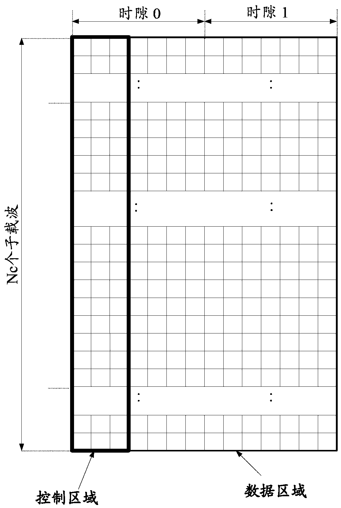
technical field [0001] The present invention relates to the field of wireless communication, in particular to a transmission method and equipment for downlink user-specific demodulation reference signals. Background technique [0002] On the legacy (Legacy) carrier of the Long Term Evolution-Advance (LTE-A) system, the Orthogonal Frequency Division Multiplexing (OFDM) symbols in a downlink subframe are divided into control regions and the data area, the control area is the first N OFDM symbols of the downlink subframe, such as figure 1 shown. Among them, the possible values ​​of N are 1, 2, 3, 4, and N=4 is only applicable to the carrier with the system bandwidth of 1.4MHz. Legacy downlink channels that carry downlink control information, such as Physical Downlink Control Channel (Physical Downlink Control Channel, PDCCH), Physical Control Format Indicator Channel (Physical Control Format Indicator Channel, PCFICH), Physical HARQ Indicator Channel (Physical Hybrid-ARQ Indi...

Claims


Application Information

Patent Timeline
Patent Type & Authority Applications(China)
IPC IPC(8): H04L27/26
Inventor 高雪娟林亚男丁昱
Owner DATANG MOBILE COMM EQUIP CO LTD
Why Eureka
Try Eureka