Process for liquefaction of natural gas

A technology of natural gas and gas, applied in the field of producing liquefied natural gas (LNG), which can solve the problems of limited expander capacity and experience, and achieve the effect of low power consumption and simple process scheme

Active Publication Date: 2014-02-12
GASCONSULT
View PDF9 Cites 9 Cited by
  • Summary
  • Abstract
  • Description
  • Claims
  • Application Information

AI Technical Summary

Problems solved by technology

[0007] -Limited ability and experience with expanders until recently

Method used


Image

  • Process for liquefaction of natural gas
  • Process for liquefaction of natural gas

Examples


Embodiment Construction

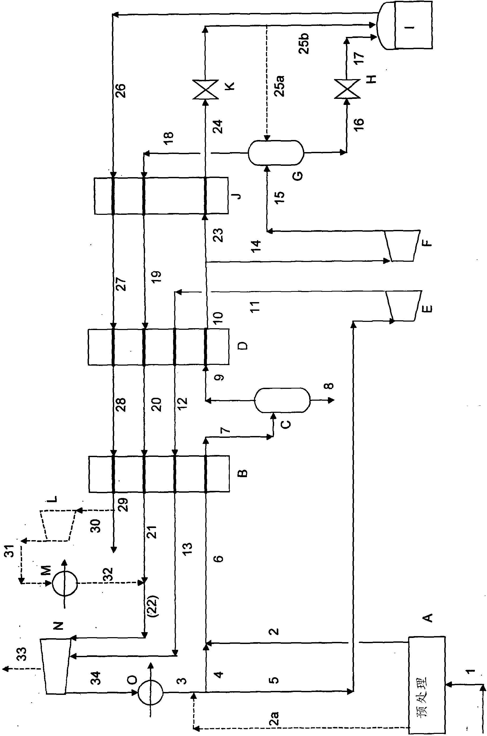
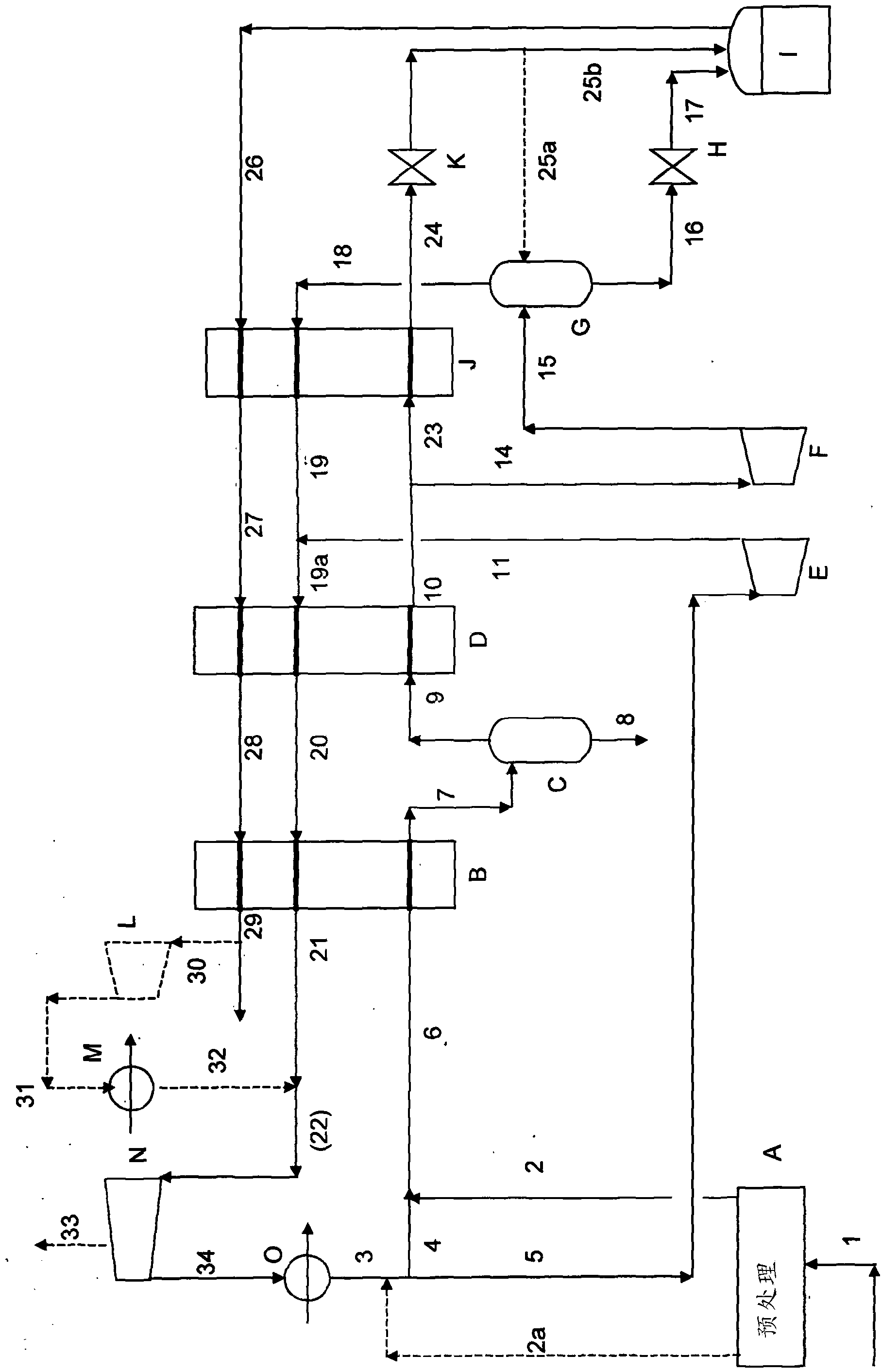
[0020] According to the present invention, there is provided a method for liquefying natural gas or other methane-rich gas. This feed gas, typically at a pressure from 40 (4Mpa) to 100 bar (10Mpa), is liquefied by the expander-based device configuration described above to produce a For LNG products, this expander-based equipment configuration includes:

[0021] - In a first step, feed gas and recycle gas (mentioned below) are passed through a first heat exchanger and cooled in a first work expander; 80°C, preferably an outlet temperature in the range of -60°C to -70°C; the expander has an outlet temperature lower than that of the heat exchanger; the outlet stream of the expander is absorbed in a cold channel of the heat exchanger Reheated and then recompressed to form part of the recycle gas described above.

[0022] - passing part of the cooled outlet stream from said first heat exchanger into a hot channel in a second heat exchanger where it is substantially condensed and ...


PUM


Abstract

A process comprising: cooling natural gas with a heat exchanger D and a first expander E. The heat exchanger D cools the feed natural gas 9 to temperature higher than the outlet temperature of the expander E, reheating the expander outlet stream 11 in a first cold passage of the heat exchanger D to slightly below the temperature of the feed natural gas 9 to the heat exchanger D, passing the cold outlet stream 14 from the heat exchanger into a second expander F wherein it is partly liquefied, separating the outlet stream 15 of second expander F into liquid 16 and vapour 18 fractions, collecting the liquid fraction 16 for use as LNG product, reheating the vapour fraction 18 in a second cold side passage of the heat exchanger D to substantially the same temperature as the temperature of the feed natural gas 9 to the heat exchanger D, recycling the reheated vapour fraction 21 partly as feed 5 to the first expander E and partly as feed 4 to the heat exchanger D. A high pressure feed gas is not required so production of LNG from smaller offshore gas fields is facilitated; the process does not rely on storage and use of liquid refrigerants.

Description

technical field [0001] The present invention relates to a method for liquefying a methane-rich gas, and more particularly, but not exclusively, to a method for producing liquefied natural gas (LNG). Background technique [0002] The liquefaction of natural gas can actually be achieved by: [0003] - Evaporate liquid refrigerant [0004] - Expansion of the gas by work in an expander (expander). [0005] Evaporation of the liquid refrigerant presents minimum power requirements and is the basis for the widely used cascade and mixed refrigerant LNG processes. [0006] Expander based LNG plants are simple, compact, low in weight and can avoid liquid refrigerant delivery / preparation / storage. These features are attractive for small scale applications (particularly offshore) where small hydrocarbon deposits are desired for safety reasons. However, the expander approach has several disadvantages: [0007] -Limited ability and experience with expanders until recently [0008] - ...

Claims


Application Information

Patent Timeline
Patent Type & Authority Applications(China)
IPC IPC(8): F25J1/00
CPCF25J1/0035F25J1/004F25J1/023F25J1/0202F25J1/0037F25J1/0254F25J2220/64F25J1/0022F25J2270/06F25J2220/62F25J1/0227F25J1/0242F25J1/0281F25J1/0283F25J2240/82F25J2270/906F25J1/0211F25J5/00F25J1/00
Inventor 安东尼·D·蒙德杰弗里·弗雷德里克·斯金纳
Owner GASCONSULT
Why Eureka
Try Eureka