
Pond auto-clean cage culture facility

An automatic net cage cleaning technology, applied in fish farming, application, animal husbandry, etc., can solve the problems of reducing fish production in ponds, limiting the length of cages, increasing the incidence of disease, etc., achieving reduced oxygen consumption in ponds, simple management, The effect of short runtime

Inactive Publication Date: 2014-02-19
太原昕美蓝波环境科技有限公司
View PDF12 Cites 21 Cited by
  • Summary
  • Abstract
  • Description
  • Claims
  • Application Information

AI Technical Summary

Problems solved by technology

[0002] At present, pond decontamination is mainly to use machines to push and dig the pond after drying the pond. The disadvantage is that it can only be carried out after the end of the breeding season. During the breeding period, the water body is seriously polluted, reducing the production of pond fish and increasing the incidence of disease.
The other is to clean up pollution through water circulation. The disadvantage is that ponds need to be transformed and special sedimentation tanks are built. The cost is high. In order to maintain a large water body, the energy consumption is high, and the scope of application is limited to smaller ponds.
The "Pond Net Cage Cleaning and Breeding System" (invention patent No. 201210249254.8) invented by the inventor has the problem of being unable to push after the dirt is deposited, causing the water quality in the cage area to deteriorate.

Method used


Image

  • Pond auto-clean cage culture facility
  • Pond auto-clean cage culture facility

Examples


Embodiment Construction

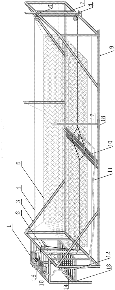
[0020] The present invention comprises net cage frame, blower fan 16, sewage suction pump 15, sewage suction pipe 10, stay rope 4, rope roller and power drive part 1, and net cage frame is made up of two angular frames 3, a rectangular frame 13, two The angular frames 3 are respectively located on both sides of the pond, and the rectangular frame 13 is connected to one of the angular frames. The sewage suction pump 15, the blower fan 16, the rope roller and the power drive part 1 are installed on the rectangular frame 13, and two Sewage suction pipe slide rail 9, a fixed pulley 2 is installed at the midpoint of the upper cross bar of the angle frame 3, two positioning bars 7 are installed on the angle frame 3, a pulley positioning bar 8 is installed between the two positioning bars 7, and the upper end has A locking ring 6 for locking the pulley positioning rod 8, a fixed pulley 2 is installed at the lower end of the pulley positioning rod 8, and the pull rope 4 is connected to...


PUM


Abstract

The invention relates to a culture device, in particular to a pond auto-clean cage culture facility capable of timely clearing dirt such as fish excrement and residual feed. The pond auto-clean cage culture facility is characterized in that a dirt suction pump, a blower and a rope roll and power drive assembly are mounted on a rectangular frame. A pull rope is wound around four fixed pulleys and connected to a rope fixing ring of a dirt suction pipe and is wound on a rope roll to form a circular line. The dirt suction pipe is disposed at two ends of the bottom of a pond and rested on a dirt suction pipe slide rail. The dirt suction pipe is connected with the dirt suction pump through a discharge hose. The blower is connected with an aerating pipe which is mounted in the pond. The rope roll and power drive assembly is composed of a motor, a reducer, and the rope roll and further comprises a rope touch switch or timing switch used for controlling a power unit to steer. When reaching the two end points, the dirt suction pipe automatically returns. The pond auto-clean cage culture facility has the advantages that modifying the culture pond is not required, water discharging or flowing water is not required, silt is removed during culturing, a scraper and the dirt suction pump automatically operate by the aid of the timing or touch switch, and the pond auto-clean cage culture facility is applicable to various water areas different in size, shape, depth and the like.

Description

technical field [0001] The invention relates to a breeding device, in particular to an automatic cleaning and breeding device for pond cages which can remove fish feces, residual bait and other dirt in time. Background technique [0002] At present, pond decontamination is mainly done after the pond is dried up and then used to push and dredge the dredging. The disadvantage is that it can only be carried out after the breeding season is over, which seriously pollutes the water body during the breeding period, reduces the production of fish in the pond and increases the incidence of disease. The other is to clean up pollution through water circulation. The disadvantage is that ponds need to be transformed and special sedimentation tanks are built. The cost is high. In order to maintain a large water body, the energy consumption is high, and the application range is limited to small ponds. The "Pond Net Cage Cleaning and Breeding System" (invention patent No. 201210249254.8) i...

Claims


Application Information

Patent Timeline
IPC IPC(8): A01K63/04
Inventor 丁建华
Owner 太原昕美蓝波环境科技有限公司
Learn More