Drawer slide rail system

A technology for drawers and slide rails, applied in the field of slide rail systems, which can solve the problems of uneven opening and closing of drawers, difficult installation and positioning, and short use

Active Publication Date: 2014-02-19
伍志勇
View PDF11 Cites 13 Cited by
  • Summary
  • Abstract
  • Description
  • Claims
  • Application Information

AI Technical Summary

Problems solved by technology

The structure is complex, the gears are arranged on the side of the drawer through the side elements, and the installation and positioning are difficult;

Method used


Image

  • Drawer slide rail system
  • Drawer slide rail system
  • Drawer slide rail system

Examples


no. 1 example

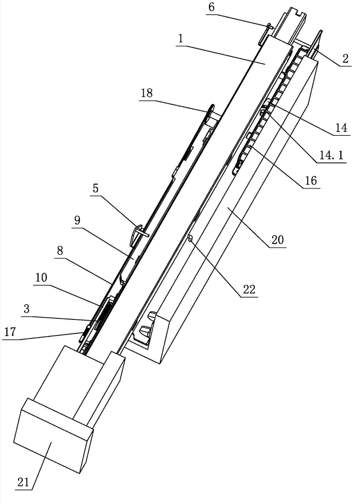
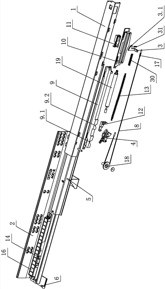
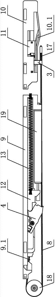
[0029] see figure 1 - Figure 4 , the drawer slide rail system includes a slide rail assembly arranged on the side panel 20 of the cabinet, the slide rail assembly is provided with a drawer, the drawer is at least composed of a bottom plate and a front panel 21, and the slide rail assembly is at least composed of a movable slide rail 1 and a fixed slide rail Rail 2, the moving slide rail 1 or the fixed slide rail 2 is provided with a damping device, and the damping device has at least a certain stroke when the drawer is closed, passing through the elastic pendulum A3 set on it and the front end of the fixed slide rail 2 or the moving slide rail 1 The setting dial A5 touches each other, and drives the sliding pendulum B4 on the damping device through a cable 8, belt or rope, so that the sliding pendulum B4 is locked on the first locking notch 9.1 of the damping device. When the drawer continues to close, the sliding pendulum bolt B4 has at least one section of stroke that touc...

no. 2 example

[0042] see Figure 19 , this embodiment is different from the first embodiment in that:

[0043] The pressing rebound device is arranged on the side panel 20 of the cabinet, and includes an elastic stopper (not shown in the figure), a moving part 14' and a spring (not shown in the figure); the elastic stopper and the moving part 14' are arranged on the sideboard 20 of the cabinet On the other hand, one end of the spring is connected with the elastic stopper, and the other end is connected with the moving part 14'; at least a part of the moving part 14' protrudes out of the side panel 20 of the cabinet, and at least passes through the spring when the drawer is opened and / or closed. The spring is loaded on the front panel 21 to realize the sliding of the moving part 14 ′ on the side panel 20 of the cabinet.

[0044] Other unmentioned parts are the same as the first embodiment.


PUM


Abstract

A drawer slide rail system comprises a slide rail subassembly, wherein the slide rail subassembly is arranged on a side plate of a cabinet and is provided with a drawer; the drawer comprises a bottom plate and a front panel; the slide rail subassembly comprises a movable slide rail and a fixed slide rail; a damping device is arranged on the movable slide rail or the fixed slide rail; when the drawer is closed, the damping device travels by a distance, and an elastic swinging plug A arranged on the damping device touches a shifting nail A arranged at the front end of the fixed slide rail or the movable slide rail; a sliding swinging plug B on the damping device is clamped in a first locking notch in the damping device by a cable, a strap or a rope; when the drawer continues being closed, the sliding swinging plug B touches a shifting nail B arranged at the rear end of the fixed slide rail or the movable slide rail, so that the sliding swinging plug B is released from the first locking notch; and the drawer is automatically closed by a damping spring. A pushing rebounding device is arranged on the movable slide rail, the fixed slide rail or the side plate of the cabinet; when closed, the drawer is automatically stopped at a position which is distant from a pre-stopping position of the side plate of the cabinet by a distance H through an elastic stopping block on the pushing rebounding device, and is positioned by elasticity; and moreover, the drawer is automatically opened by the elastic stopping block.

Description

technical field [0001] The invention relates to a slide rail system, in particular to a drawer slide rail system. Background technique [0002] Chinese patent document CN101316530A disclosed a drawer on December 3, 2008, which can move from a position in the furniture to a pull-out position in front of the furniture through a pull-out guide device relative to the furniture, wherein the drawer is in the opposite position. There is at least one toothed wheel on each of the opposite sides, which meshes with a toothed rack fixed on the furniture body and is connected with a toothed wheel on the opposite side, each toothed rack can be lengthened via a deflectable rod , thereby also ensuring that the drawer is guided by the gears in the pulled-out position, a deflectable rod can be disengaged from the engaged gears so that the skewed position of the drawer can be corrected, thus ensuring that the drawer is guided by the gears throughout its travel. The structure is complex, the g...

Claims


Application Information

Patent Timeline
Patent Type & Authority Applications(China)
IPC IPC(8): A47B88/04A47B88/10A47B88/493
Inventor 伍志勇
Owner 伍志勇
Why Eureka
Try Eureka