
Electrolytic manganese dioxide cyclone separator

A technology of electrolytic manganese dioxide and cyclone separator, which is applied to cyclone devices, devices whose axial directions of cyclones can be reversed, etc. The effect of good thermal insulation, improved structure, strong rotation effect

Inactive Publication Date: 2014-02-19
GUANGXI GUILIU CHEM CO LTD
View PDF5 Cites 8 Cited by
  • Summary
  • Abstract
  • Description
  • Claims
  • Application Information

AI Technical Summary

Problems solved by technology

The effect of particle separation is related to the temperature, humidity, gas velocity, particle size and weight of the airflow, and the diameter of the separator shell. In addition, the complexity of the internal swirl movement makes it difficult to separate the cyclone separator. make a precise description

Method used


Image

  • Electrolytic manganese dioxide cyclone separator

Examples


Embodiment 1

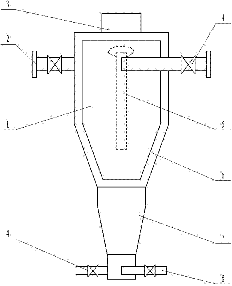
[0023] An electrolytic manganese dioxide cyclone, comprising a cylinder body 1, an air inlet pipe A2 and an air outlet pipe 3, the upper part of the cylinder body 1 is a cylinder, the lower part is a cone, and a cylinder at the upper end of the cylinder body 1 An air inlet pipe A2 is arranged at the tangent of the outer wall, and the said air inlet pipe A2 is two, and the two air inlet pipes A2 are on the same horizontal plane and are parallel to each other. An air outlet pipe 3 is arranged at the upper end cap of the cylinder body 1, and a vortex stabilization pipe 5 is arranged directly below the air outlet pipe 3 in the cylinder body 1, and the diameter of the vortex stabilization pipe 5 is smaller than the diameter of the air inlet pipe A2 . A cyclone joint 7 is provided at the lower end of the cylindrical body 1 , and an air inlet pipe B8 is arranged on the cyclone joint 7 . There are two air inlet pipes B8, and the two air inlet pipes B8 are on the same horizontal plane...

Embodiment 2

[0026] An electrolytic manganese dioxide cyclone, comprising a cylinder body 1, an air inlet pipe A2 and an air outlet pipe 3, the upper part of the cylinder body 1 is a cylinder, the lower part is a cone, and a cylinder at the upper end of the cylinder body 1 The air inlet pipe A2 is set at the tangent of the outer wall. The air inlet pipe A2 is two, and the two air inlet pipes A2 are on the same horizontal plane and are parallel to each other. The air outlet pipe 3 is set at the upper end cover of the cylinder 1 , a vortex stabilization tube 5 is arranged directly below the air outlet pipe 3 in the cylindrical body 1, and the diameter of the vortex stabilization tube 5 is smaller than the diameter of the air inlet pipe A2. The outer layer of the cylinder body 1 is provided with a vacuum chamber 6 , and a vacuum valve is arranged on the vacuum chamber 6 . A cyclone joint 7 is arranged at the lower end of the cylinder body 1 ; an air inlet pipe B8 is arranged on the cyclone jo...


PUM


Abstract

The invention discloses an electrolytic manganese dioxide cyclone separator which comprises a barrel body, two air inlet pipes A and an air outlet pipe, wherein the upper part of the barrel body is a cylinder, and the lower part of the barrel body is a cone; the air inlet pipes A are arranged at tangent positions on the outer wall of the cylinder at the upper end of the barrel body; the air outlet pipe is arranged at the cover of the upper end of the barrel body; a vortex stabilization pipe is arranged under the air outlet pipe in the barrel body; a cyclone joint is arranged at the lower end of the barrel body; two air inlet pipes B are arranged on the cyclone joint. According to the electrolytic manganese dioxide cyclone separator, the structure of an inner flow field of the cyclone separator is effectively improved, and the pressure loss of the cyclone separator is reduced; furthermore, the electrolytic manganese dioxide cyclone separator can effectively implement secondary separation, so that the quality of a separated material is improved, and the requirement on electrolytic manganese dioxide production is met. The electrolytic manganese dioxide cyclone separator is simple and reasonable in structure, wide in application range and suitable for popularization and application.

Description

technical field [0001] The invention belongs to a separation device for discrete phases in a multiphase flow, in particular to an electrolytic manganese dioxide cyclone separator. Background technique [0002] Electrolytic manganese dioxide is an excellent positive electrode material for batteries. Compared with dry batteries produced by natural discharge manganese dioxide, it has the characteristics of large discharge capacity, strong activity, small size and long life. Therefore, electrolytic manganese dioxide has become the most popular in the battery industry. a very important raw material. In the production process of electrolytic manganese dioxide, a cyclone separator is installed above the grinding chamber. The high-speed rotation of the separator generates negative pressure, and the qualified products that reach a certain particle size of fine powder will be sucked into the cyclone separator and separated . [0003] The traditional cyclone has a simple structure, a...

Claims


Application Information

Patent Timeline
Patent Type & Authority Applications(China)
IPC IPC(8): B04C5/00B04C5/04B04C5/103
Inventor 闭越斌覃光普陈建强刘启松邓洪陆云平
Owner GUANGXI GUILIU CHEM CO LTD
Learn More