A method for milling and slotting an open blisk

An integral blisk and groove processing technology, applied in metal processing equipment, milling machine equipment, manufacturing tools, etc., can solve the problems of large material removal, easy tool wear, low processing efficiency, etc., to improve forming quality and processing time. , the effect of improving the removal rate

Inactive Publication Date: 2015-11-18
HARBIN UNIV OF SCI & TECH
View PDF1 Cites 2 Cited by
  • Summary
  • Abstract
  • Description
  • Claims
  • Application Information

AI Technical Summary

Problems solved by technology

[0004] The purpose of the present invention is to provide a method for milling and slotting an open blisk disc to solve the problem of large amount of material removal and low processing efficiency in the rough machining and slotting process of the open blisk channel, and due to the The channel is narrow and deep, the tool is easy to interfere with the free-form surface blade, and the tool is easy to wear

Method used


Image

  • A method for milling and slotting an open blisk
  • A method for milling and slotting an open blisk
  • A method for milling and slotting an open blisk

Examples


specific Embodiment approach 1

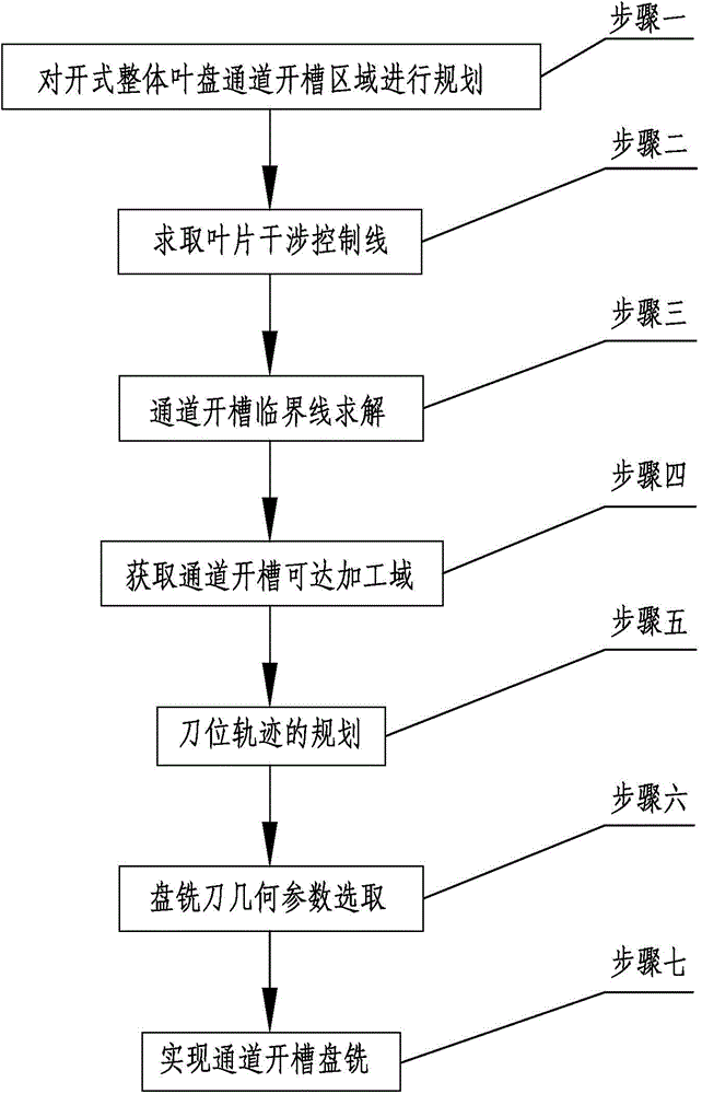
[0037] Specific implementation mode one: as Figure 1-Figure 6 As shown, an open-type blisk disc milling and slotting processing method according to this embodiment, the open-type blisk disc milling and slotting processing method includes the following steps:

[0038] Step 1: Plan the grooved area of ​​the open blisk channel;

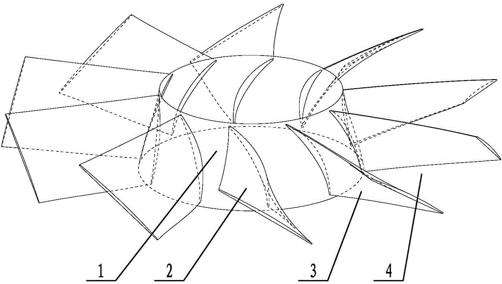
[0039] First define a set of sectional planes perpendicular to the axis of the blisk, and then intercept a set of ring curves intersecting the surface of the blisk channel ring hub (the channel ring hub is the ring hub part in the channel), and in this set of ring curves Find the point with the largest distance from the blisk axis; pass this point and the plane of the blisk axis, and then draw a straight line through the said point in this plane, so that the straight line is parallel to the blisk axis; then use this line as the generatrix Rotate around the axis of the blisk to get the slotted inner ring surface of the blisk; divide the blade into a con...

specific Embodiment approach 2

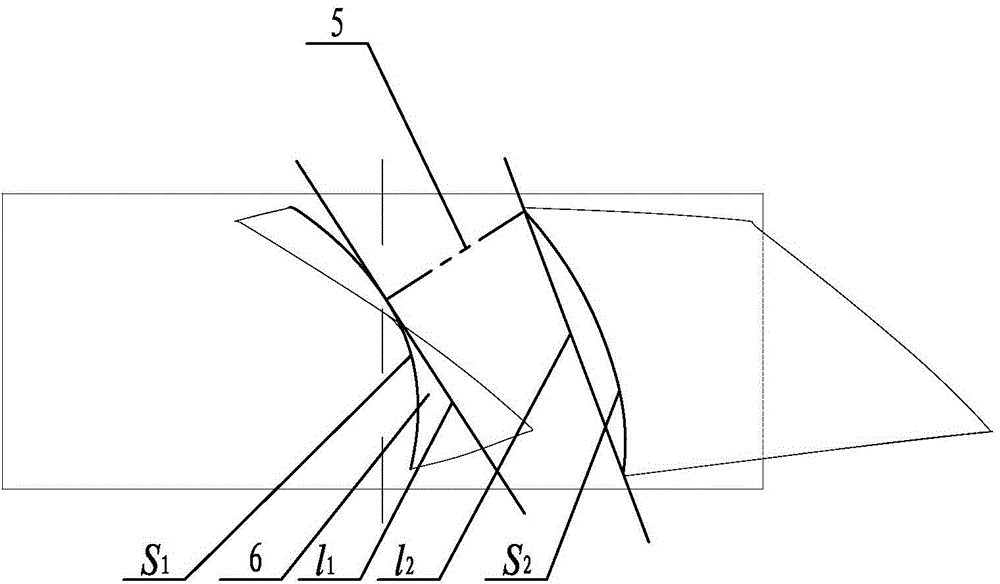
[0055] Specific implementation mode two: combination image 3 Note that in step 2 of this embodiment, the calculation of the length of the blade interference control line 5 is calculated by the method of calculating the minimum distance between curved surfaces based on the principle of surface geometry or based on UG computer-aided design software. The obtained blade interference control line 5 has a length of 19.73mm. The undisclosed technical features in this embodiment are the same as those in the first embodiment.

specific Embodiment approach 3

[0056] Specific implementation mode three: in step six of this embodiment, the blade width E of the supporting blade of the cutter body is determined by the blisk material and the offset surface-L in step five 11 parallel to the plane-L 01 , select the offset surface 2 L 22 with parallel plane II L 02 The geometric spacing (fixed groove spacing) is 10mm, so that E<10+nε. The undisclosed technical features in this embodiment are the same as those in the first or second specific embodiment.


PUM


Abstract

The invention discloses a method for disc-milling grooving processing on an open-type blisk. The method solves the problem that the existing open-type blisk channel rough grooving process has a large material removal amount and low processing efficiency, and produces interference between a cutter and a free-form surface blade because of narrow and deep grooving channels so that the cutter is worn easily. The method comprises the following steps of planning an open-type blisk channel grooving area, calculating a blade interference control line, calculating a channel grooving critical line, acquiring a channel grooving reachable processing area, planning a cutter position track, selecting disc-milling cutter geometrical parameters, and carrying out channel grooving disc-milling. The method is suitable for open-type blisk grooving disc-milling.

Description

technical field [0001] The invention relates to a method for slotting a blisk disc milling channel. Background technique [0002] The open blisk is an important part of modern high thrust-to-weight ratio aero-engines. CNC milling is the main manufacturing method, but the existing technology mainly has the following problems: 1) The blade profile of the open blisk is complex and free space. Curved surface, large blade twist, narrow and deep channel, resulting in interference problems in the CNC machining process; 2) The existing slotting methods include end milling layered slotting, side milling and plunge milling methods, end milling and The side milling method is inefficient and not suitable for deeper channels. Although the efficiency of plunge milling has been improved, it is still difficult to meet the high-efficiency slotting requirements; 3) The existing slotting tools mainly include cylindrical flat-bottomed cutters and conical ball cutters And special plunge milling...

Claims


Application Information

Patent Timeline
Patent Type & Authority Patents(China)
IPC IPC(8): B23C3/18
Inventor 程耀楠安硕张悦刘献礼
Owner HARBIN UNIV OF SCI & TECH
Why Eureka
Try Eureka