Machining center

A machining center and mounting rod technology, which is applied in metal processing equipment, metal processing mechanical parts, manufacturing tools, etc., can solve the problem that the machining center is difficult to apply to mass production, and achieve the effect of improving processing efficiency and improving processing efficiency.

Inactive Publication Date: 2014-02-19
宁波优尔机械有限公司
View PDF6 Cites 9 Cited by
  • Summary
  • Abstract
  • Description
  • Claims
  • Application Information

AI Technical Summary

Problems solved by technology

This is one of the reasons why machining centers are difficult to apply to mass production

Method used


Image

  • Machining center
  • Machining center
  • Machining center

Examples


Embodiment Construction

[0018] The present invention will be further described below with reference to the accompanying drawings and specific embodiments.

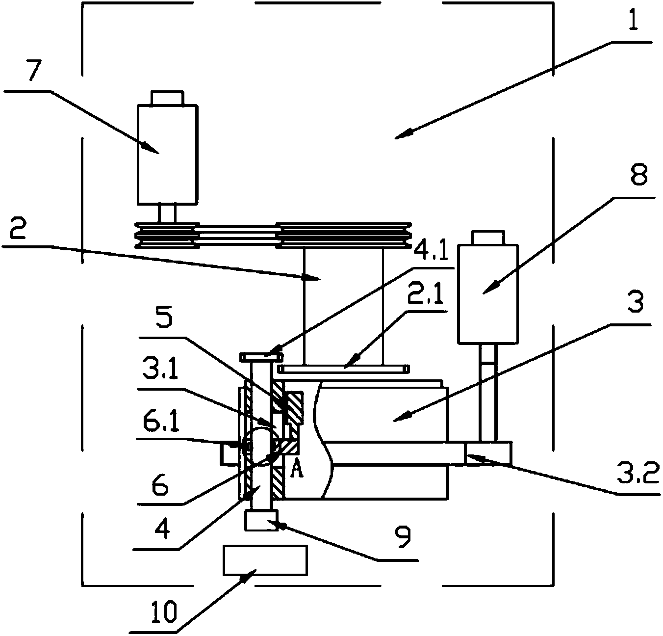
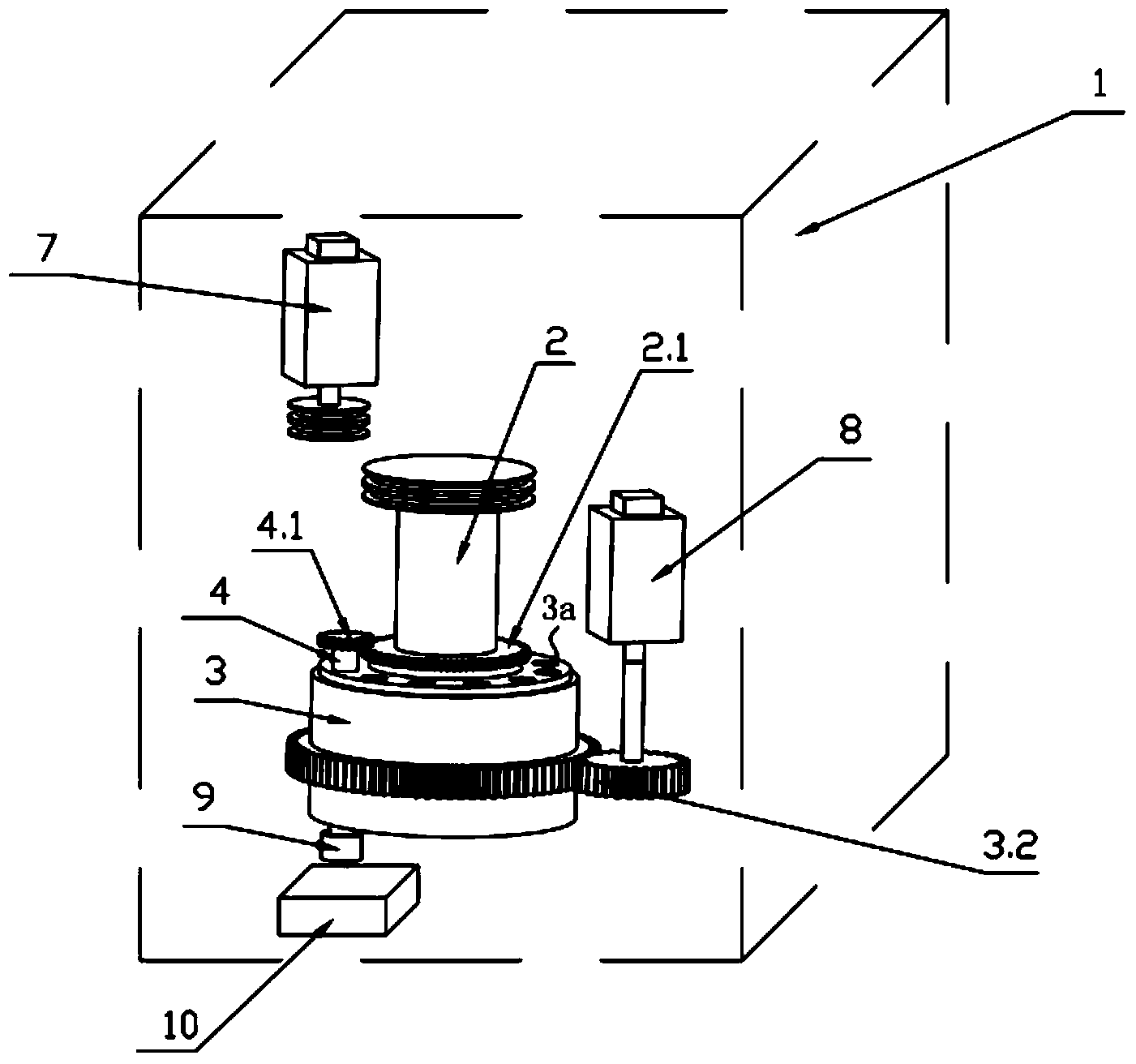
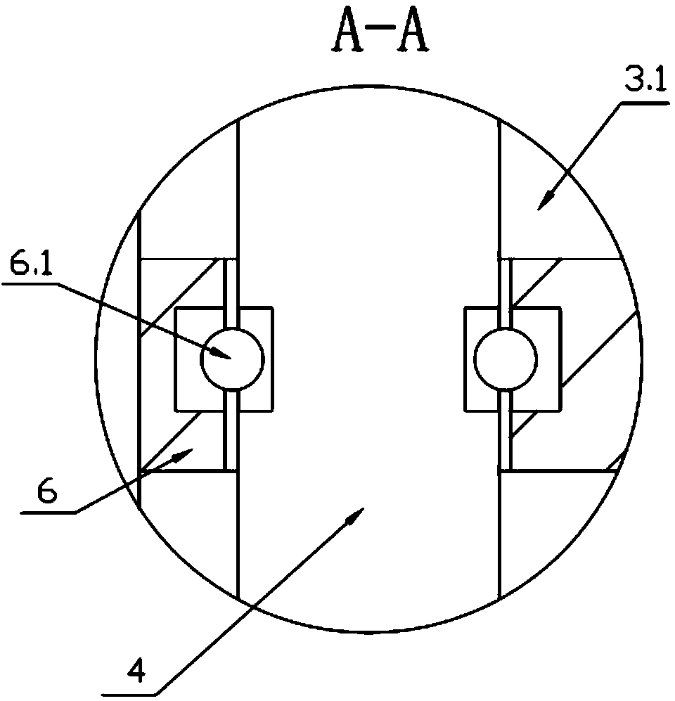
[0019] like figure 1 As shown, the machining center of the present invention includes a main body 1, a driving shaft 2 arranged on the main body 1 and driven to rotate by a first motor 7, and a tool magazine 3 driven to rotate by a second motor 8. The first The motor 7 and the second motor 8 are both electrically connected to the control unit, that is, the start and stop of the first motor 7 and the second motor 8 are automatically controlled through the control panel of the machining center. The axis of the tool magazine 3 is perpendicular to the upper surface of the workpiece 10 to be processed. The tool magazine 3 is provided with through holes of the same circle and evenly distributed for accommodating the mounting rods 4 of different tools 9. The mounting rods 4 slides and rotates to fit in the through hole, and the bottom end of each insta...


PUM


Abstract

The invention discloses a machining center which comprises a main body (1), a driving shaft (2) and a tool magazine (3). The axis of the tool magazine (3) is vertical to the upper surface of a workpiece to be machined (10), the tool magazine (3) is evenly provided with through holes which are concentric and used for containing installation rods (4) of cutters (9), the installation rods (4) are rotatably arranged in the through holes in a sliding and matched mode, the bottom ends of the installation rods (4) are provided with different cutters (9), a transmission capable of being disengaged is arranged between the installation rods (4) and the driving shaft (2), and the tool magazine (3) is provided with a telescopic mechanism which can drive the installation rods (4) to slide up and down to achieve disengaging or connection of the transmission mechanism and can be positioned at any position. By means of the structure, other mechanical arms are not needed for the cutter replacing process and the cutter assembling process, so that the whole cutter replacing process is quicker and machining efficiency is improved.

Description

technical field [0001] The present invention relates to a machining center. Background technique [0002] In the field of modern machining, machining centers, as a kind of high-precision automatic processing equipment, are more and more applied to high-precision machining centers due to their concentrated processes, high machining accuracy and automatic tool change. Parts are being processed. Especially for some small batch parts with complex shapes and high precision requirements, their processing methods are often completed by high-precision machining centers. For conventional machining centers, the machining process is often that a spindle rotates to drive a tool to process parts. Due to the complexity of the shape of the parts, it is necessary to replace the tool frequently, and the steps of changing the tool are generally first. The tool magazine rotates to select the tool to be used, then the manipulator works to complete the tool change, and finally the tool is load...

Claims


Application Information

Patent Timeline
Patent Type & Authority Applications(China)
IPC IPC(8): B23Q3/157
CPCB23Q3/15766B23Q5/10
Inventor 盛光伟许华良
Owner 宁波优尔机械有限公司
Why Eureka
Try Eureka