Portable apparatus for working, shaping and polishing stone and other hard materials

a technology for working tools and other hard materials, applied in the field of stoneworking, can solve the problems of inconvenient use of stone for work in situ at a construction location or the like, undetectable large amounts of very expensive idle time, and reduce hand labor. , the effect of improving the precision of cutting and polishing operations

Inactive Publication Date: 2006-02-14
KALB ROBERT M
View PDF2 Cites 4 Cited by
  • Summary
  • Abstract
  • Description
  • Claims
  • Application Information

AI Technical Summary

Benefits of technology

[0017]Exemplary embodiments of the present invention solve inadequacies of the prior art by providing a portable trolley for carrying various tools, and a track which attaches directly to a stone and which simultaneously isolates tool from stone. A standard connection is provided which can readily accommodate a variety of diverse tools, using a keyway to ensure accurate and repeatable placement of the tools. A preferred contouring guide allows a tool to be moved through an arc, where the focal point of the arc may be set to produce an infinite variety of custom shapes.
[0018]A first object of the invention is to provide a portable tool guide for stone and other hard materials. A second object of the invention is to greatly reduce the hand labor required to custom finish a hard material. Another object of the present invention is to improve the precision of cutting and polishing operations. A further object of the invention is to provide the guide in a relatively small and compact package. Yet another object of the present invention is to enable rapid tool changes. Yet a further object of the invention is to provide a precision shaper using low cost and durable disc-shaped abrasives, to accurately produce a diverse number of edge profiles. Another object of the invention is the provision of a high quality, precision tool guide which is durable and still manufactured for a low cost. An additional object of the invention is to provide an apparatus that automatically adjusts for abrasive material lost from the cutter. Another object of the invention is to provide a portable apparatus that may be manually controlled or controlled through electrical devices. Another object of the invention is to provide an apparatus that will work surfaces that may be warped or otherwise less than perfectly level. A further object of the invention is to provide a means for rapidly controlling the break line profile between stone surface and stone edge.

Problems solved by technology

As is known in the industry, the cutting, shaping and polishing operations release a large quantity of abrasive in the form of slurry and dust which can be quite detrimental to machines and equipment which are not designed to withstand the erosive environment.
While these tools are well suited for operations where stones may be readily transported to the machine, they clearly have no utility for stones to be worked in situ at a construction location or the like.
Furthermore, these machines tend to be extremely expensive, and so custom production on this type of machine results in undesirably large amounts of very expensive idle time.
Not only do stones need to be changed for custom production, but the machine will also typically require reconfiguration and / or realignment for the custom job.
Furthermore, the transport of a stone to and from a construction site to effect the custom work is not only expensive and the source of much delay, but the likelihood of an accident which destroys the stone is much greater with the additional transport.
Finally, these large machines tend to be cost-prohibitive for a smaller shop that is not continuously using the machine.
The profiled cutter is an abrasive, and is generally extremely expensive.
With the nature of grinding, the abrasive on the profiled cutter is lost, generally unevenly.
When a section of flooring or wall requires custom cutting and fitting, it is not always practical or reasonable to expect a stone factory to size the stone to the needs in advance.
Moreover, it may not always be possible to accurately predict the dimensions owing to variability such as spacing between adjacent stone and the like.
Furthermore, the thickness of adjacent stones may vary somewhat unpredictably, and the leveling of the intersection of the two stones may be a very important finishing operation.
Unfortunately, many of these devices are designed for only very light duty.
Where guides are used, they tend to lack the necessary resistance to abrasion from the stoneworking dust, and consequently have a limited life only suited for very light duty stone working.
This single function tool holding and guiding is not highly desirable, and so many masons will perform all but the most complex or sizeable jobs by hand.
As is all too well known, when work is completed by hand, there is much greater risk that the mason will err in the process, and this error is not readily remediated in stone.
Additionally, the freehand shaping and polishing is very strenuous and time consuming.
Moreover, adjacent to the sink the stone will frequently be rather narrow.

Method used


Image

  • Portable apparatus for working, shaping and polishing stone and other hard materials
  • Portable apparatus for working, shaping and polishing stone and other hard materials
  • Portable apparatus for working, shaping and polishing stone and other hard materials

Examples


embodiment 100

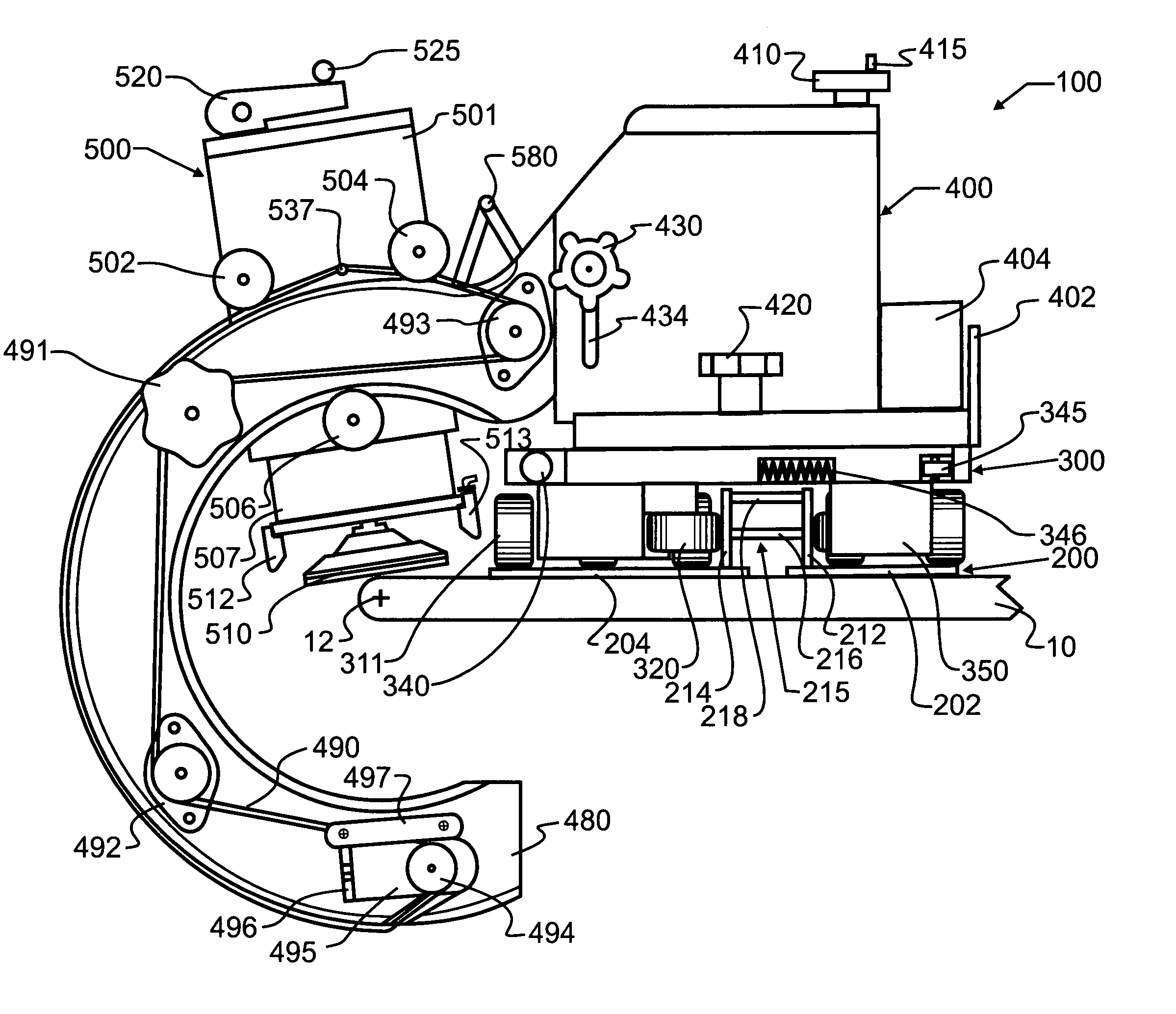
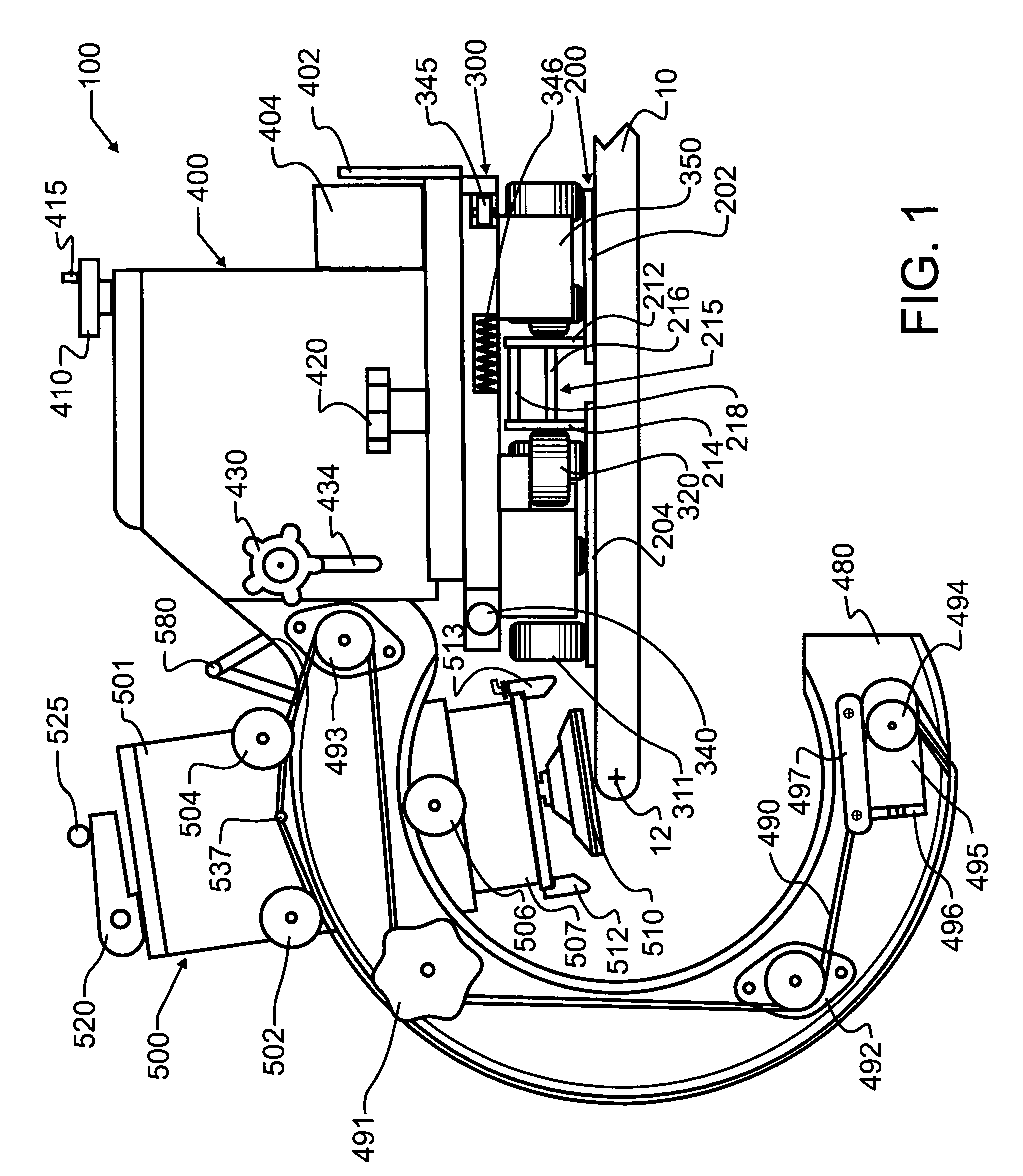
[0036]Trolley 300 acts as a support for a tool carrier 400 which is secured thereto. Tool carrier 400 as presently illustrated comprises a pair of crescents 470, 480 which are most preferred for the flat abrasive discs used in the preferred embodiment 100. However, those skilled in the field will recognize that the preferred embodiment trolley 300 is compatible with other structures which are known to mate with circular saws carrying diamond or other abrasive wheels, routers, and other stoneworking tools. Between crescents 470, 480 is mounted tool support carriage 500.

[0037]As illustrated in FIG. 1, crescents 470, 480 combine to form a central axis of rotation 12. Axis 12 will extend parallel to rail 215 and will be centered at the focal point of crescents 470, 480. However, once again those skilled in the field will recognize that it is not essential to form crescents 470, 480 into a circular geometry as illustrated, though this geometry is typically the most versatile. Other shape...

first embodiment

[0073]To address this need for both flexibility and rigidity, a first embodiment stiffener 800 is illustrated in FIG. 15. As may be seen therein, track 201 has a profile with two t-slots 203, 205 that run parallel to its length. The front slot 205 that is closest to crescents 470, 480 is underneath the trolley 300 center of balance. In this front slot 205 the operator will slide stiffener 800, to hold track 201 to stone or other work piece 10. After clamp 802 is secured, by placing bolts 804 and tightening screw 806 in the preferred embodiment, there is a bracket-like member 808 that pivots about hinge 807 relative to tightening screw 806. By rotating thumbscrew 809, bracket 808 will push away from clamp 802, thereby creating additional support for the end of track 201. Most preferably, thumbscrew 809 will be rotated sufficiently to make the ends of track 201 beyond work piece 10 rigid enough to support the weight of trolley 300, while track 201 remains relatively more flexible in t...

second embodiment

[0077]A second embodiment stiffener 810 is shown in FIG. 17. As illustrated therein, a specially shaped body member 818 is slid into either groove 203, 205 or both, and screw 806 tightened. The force of screw 806, owing to the intrinsic geometry of member 818, will cause member 818 to apply an upward deflection force to track 201.

[0078]As illustrated and described herein above with reference to the preferred embodiments, the present invention provides a means to shape and polish a perfect edge. The preferred embodiment is, lightweight enough for one person to carry, can be used in the field, and utilizes inexpensive abrasives. The method of shaping and polishing is safer than in the prior art, since the operator's hands are farther away from the cutter. The operator's hands are also available to control the various hoses, cords and valves. Since the weight of the apparatus is bearing on the stone slab, the physical nature of manual shaping and polishing has been made less strenuous....


PUM

PropertyMeasurementUnit
driving forceaaaaaaaaaa
massaaaaaaaaaa
heightaaaaaaaaaa

Abstract

A wheeled trolley carries various tools across an object to be worked. A track attaches directly to the work and simultaneously isolates the tool from the work. A standard connection to the trolley readily accommodates a variety of diverse tools, using a keyway or the like to ensure accurate and repeatable placement of the tools. A preferred contouring guide allows a tool to be moved through an arc, where the focal point of the arc may be set to produce an infinite variety of custom shapes, bevels or angles of cut. An upper stop is provided which readily sets the break line between surface finish and edge contour. An adjustable tool carriage allows control over both position and force, including preloading a work tool with force. Resilience is incorporated into the apparatus to accommodate diverse hardness and abrasion characteristics, and, in at least one embodiment, to enable the track to accurately follow a warped or sagging work piece.

Description

CROSS REFERENCE TO RELATED APPLICATIONS[0001]This application is a continuation-in-part of U.S. application Ser. No. 10 / 081,965 filed Feb. 20, 2002 Now U.S. Pat. No. 6,712,061 presently allowed and copending herewith and listing the present title and inventor, and which in turn claims priority to U.S. Provisional patent application Ser. No. 60 / 269,721 filed Feb. 20, 2001, the contents of each which are incorporated by reference in entirety.BACKGROUND OF THE INVENTION[0002]1. Field of the Invention[0003]This invention pertains generally to the field of stoneworking, and more specifically to sawing, shaping and polishing of stone or similar material. Various specific manifestations of the invention include a portable tool mount which is configured to support and guide a saw, an abrading rotary disk tool, or other stoneworking equipment or tools; an edging apparatus for stone and other hard materials; and a rotary disk abrading tool provided with a member or a holder to facilitate the ...

Claims


Application Information

Patent Timeline
Patent Type & Authority Patents(United States)
IPC IPC(8): B28D1/04B23D45/02B23D47/02B23Q9/00B24B9/06B24B41/04B28DB28D1/00
CPCB23D45/024B23D45/027B23D47/02B23Q9/0014B24B41/04B28D1/003B28D1/045B24B9/06B23Q2210/006
Inventor KALB, ROBERT M.
Owner KALB ROBERT M
Why Eureka
Try Eureka