High-speed ultrasonic automatic tool changing motorized spindle

An automatic tool changing and ultrasonic technology, applied in the direction of large fixed members, metal processing machinery parts, maintenance and safety accessories, etc., can solve the problems of large processing resistance, low processing efficiency, low processing roughness, etc., and achieve small processing stress, Effects of improving processing efficiency and improving roughness

Active Publication Date: 2016-09-07
江苏翰琪电机股份有限公司
View PDF7 Cites 5 Cited by
  • Summary
  • Abstract
  • Description
  • Claims
  • Application Information

AI Technical Summary

Problems solved by technology

The overall processing resistance in the prior art is large, the processing efficiency is low, and the processing roughness is low

Method used


Image

  • High-speed ultrasonic automatic tool changing motorized spindle
  • High-speed ultrasonic automatic tool changing motorized spindle
  • High-speed ultrasonic automatic tool changing motorized spindle

Examples


Embodiment 1

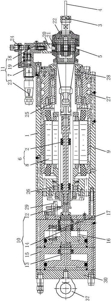
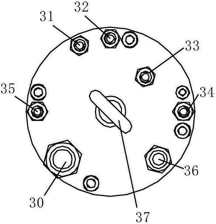
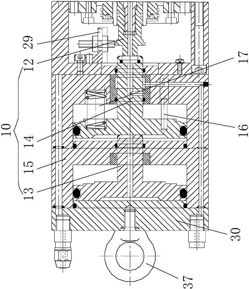
[0024] See Figure 1 to Figure 4 , the present invention relates to a high-speed ultrasonic automatic tool change electric spindle, which has an ultrasonic spindle; the ultrasonic spindle includes a casing 1, a rotor shaft 2 coaxially arranged with the casing 1, and a rotor shaft 2 fixed on the end of the rotor shaft 2 through a nut and The processing tool 4 connected by the elastic collet 3; the front end of the rotor shaft 2 is provided with a tool handle ultrasonic tool handle 22, and the rear end of the rotor shaft 2 extends into the rear end of the casing 1; the ultrasonic tool handle 22 is provided with a built-in assembly room; The built-in transducer 5 is detachably installed in the built-in assembly room; the front end of the rotor shaft 2 is provided with a front bearing assembly 25, and the rear end is provided with a rear bearing assembly 26; the outer side of the front bearing assembly 25 is provided with a front end cover 27; It is sealed and connected with the c...


PUM


Abstract

The invention relates to a high-speed ultrasonic automatic tool changing motorized spindle. The high-speed ultrasonic automatic tool changing motorized spindle is provided with an ultrasonic spindle body. The ultrasonic spindle body comprises a machine shell, a rotor shaft coaxially arranged with the machine shell, and a machining tool fixed to one end of the rotor shaft and connected with the end of the rotor shaft through nuts and an elastic contracting chuck. An ultrasonic tool handle is arranged at the front end of the rotor shaft. The rear end of the rotor shaft extends into the rear end of the machine shell. A built-in type assembly chamber is arranged in the ultrasonic tool handle. A built-in energy converter is detachably mounted in the built-in type assembly chamber. An ultrasonic generator is mounted on the upper portion of the ultrasonic tool handle and comprises an L-shaped combined support, a planar adjusting support and a vertical adjusting support, and the planar adjusting support and the vertical adjusting support are mounted on the combined support. The planar adjusting support passes through a fixed ring and then is coupled with a movable ring on the ultrasonic tool handle. A gap is formed between the fixed ring and the movable ring. A driving motor is directly connected with the ultrasonic spindle body and the ultrasonic tool handle, and the spindle has the characteristics that the ultrasonic spindle body and the ultrasonic tool handle are mutually independent, and application is convenient.

Description

technical field [0001] The invention relates to the technical field of electromechanical transmission devices, in particular to a high-speed ultrasonic automatic tool-changing electric spindle. Background technique [0002] The existing CNC machining center adopts the ultrasonic energy-assisted method, combined with the high-speed rotation of the machine tool, to process hard and brittle materials. In ultrasonic-assisted machining, ultrasonic energy is the most critical parameter of the machining process, which can excite the atomic energy of the material and reduce the cutting force. The transducer is the core actuator that provides ultrasonic energy in ultrasonic machining. Its working principle is to use the piezoelectric inverse effect to convert frequency electrical signals into high-frequency ultrasonic vibrations, and transmit ultrasonic energy to the processed materials. As the carrier of ultrasonic energy transmission, the transducer's working performance directly ...

Claims


Application Information

Patent Timeline
Patent Type & Authority Applications(China)
IPC IPC(8): B23B19/02B23Q11/12B23Q5/58
CPCB23Q1/70B23Q5/58B23Q11/127
Inventor 钱程李明李启元钱翰琪
Owner 江苏翰琪电机股份有限公司
Why Eureka
Try Eureka