Rail vehicle braking signal transmission circuit

A technology for braking signals and rail vehicles, which is applied to the operating mechanism of railway vehicle brakes, brakes, and railway braking systems. It can solve the problems of high transmission accuracy, susceptibility to interference, and long transmission distance to improve accuracy. and safety, simple circuit design, and strong anti-interference ability

Active Publication Date: 2014-02-19
NANJING CRRC PUZHEN HAITAI BRAKE EQUIP CO LTD
View PDF6 Cites 3 Cited by
  • Summary
  • Abstract
  • Description
  • Claims
  • Application Information

AI Technical Summary

Problems solved by technology

For braking commands from the driver's handle or ATO, the transmission distance is relatively long (150-200m), the transmission accuracy is high, and the analog voltage transmission is susceptible to interference. The 4-20mA current loop transmission has high requirements on the signal source and transmission line. The cost of transmission in this way is higher

Method used


Image

  • Rail vehicle braking signal transmission circuit
  • Rail vehicle braking signal transmission circuit
  • Rail vehicle braking signal transmission circuit

Examples


Embodiment

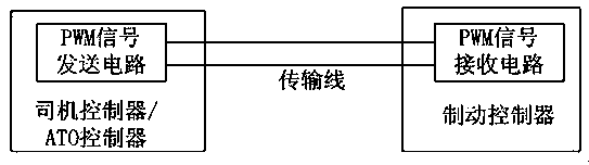
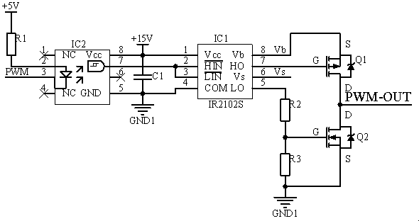
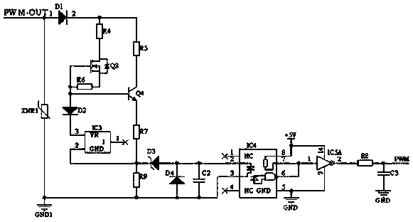
[0023] A rail vehicle braking signal transmission circuit provided in this embodiment, such as Figure 1 to Figure 3 As shown, it includes a sending circuit and a receiving circuit connected by a transmission line; the sending circuit includes a first optocoupler IC2 and a high-low driver IC1 (HIGH AND LOW) whose input terminal (HIN AND LIN) is connected to the output terminal of the first optocoupler IC2 SIDE DRIVER); the positive pole of the input terminal of the first optocoupler IC2 is connected to the low-voltage power supply 5V through the current-limiting resistor R1, and the negative pole is connected to the PWM signal to be transmitted; the high-voltage output terminal (HO) of the high- and low-end driver IC1 is connected to an N-channel enhanced The gate of the type field effect transistor Q1; the low-voltage output terminal (LO) of the high-low end driver IC1 is connected in series with the first resistor R2 and the second resistor R3 in sequence, and then connected ...


PUM


Abstract

The invention relates to a rail vehicle braking signal transmission circuit, and belongs to the technical field of rail transit communication. The rail vehicle braking signal transmission circuit comprises a transmitting circuit and a receiving circuit, wherein the transmitting circuit and the receiving circuit are connected through a transmission line, the transmitting circuit is composed of an isolation optocoupler, a high-low end driver and a field-effect transistor and used for stepping up a PWM signal with a TTL level to a high voltage PWM signal, and the receiving circuit is used for stepping down the high voltage signal through leakage currents of the field-effect transistor. According to the rail vehicle braking signal transmission circuit, transmission of the high voltage PWM signal is adopted for replacing direct long-distance transmission of an analog signal in a traditional circuit, so that the rail vehicle braking signal transmission circuit has the advantages of being simple in circuit design, strong in anti-jamming capability and high in transmission accuracy; when the rail vehicle braking signal transmission circuit is applied to a subway vehicle braking controller to receive an important rigid line signal according to a braking instruction, accuracy and safety of subway train braking can be improved remarkably.

Description

technical field [0001] The invention relates to a rail vehicle braking signal transmission circuit, which belongs to the technical field of rail traffic communication. Background technique [0002] At present, the control information and status data of rail vehicles are transmitted by MVB, RS-485 and other bus communication methods, but for signals with high importance such as braking commands, hard-wire signal transmission is designed for redundancy. In order to achieve precise braking, the braking command of the current urban rail train is usually a continuously changing analog quantity. At this stage, the transmission of the analog quantity signal of the rail vehicle mostly uses a voltage signal or a 4-20mA current. For braking commands from the driver's handle or ATO, the transmission distance is relatively long (150-200m), the transmission accuracy is high, and the analog voltage transmission is susceptible to interference. The 4-20mA current loop transmission has high ...

Claims


Application Information

Patent Timeline
Patent Type & Authority Applications(China)
IPC IPC(8): B60T8/17B61H13/00
Inventor 赵飒杨正专唐永明孙卫兵
Owner NANJING CRRC PUZHEN HAITAI BRAKE EQUIP CO LTD
Why Eureka
Try Eureka