Take-up and pay-off device applied to mobile device

A technology for retracting and unwinding devices and mobile equipment, which is applied in the field of cable winding devices, which can solve problems such as pedestrians falling, short circuits, metal objects falling into the ditch, etc., and achieve the effects of avoiding sprains, simplifying the system structure, and not consuming electric energy

Inactive Publication Date: 2014-02-19
ANHUI TONGFENG ELECTRONICS
View PDF7 Cites 12 Cited by
  • Summary
  • Abstract
  • Description
  • Claims
  • Application Information

AI Technical Summary

Problems solved by technology

For example, in the film stretching production line, the round-trip transportation of steel coil cores and large film rolls at the winding station, and the slitting and transportation of large film rolls are all completed by film transport vehicles. The body of this film transport vehicle is designed separately from the control cabinet. There are quite a lot of power cables and control cables between the car body and the control cabinet to complete the power supply and signal transmission tasks. The cable connection between the car body and the control cabinet often uses cable trenches excavated on the ground to pass the cables in the tank chain. When the vehicle body moves, the tank chain and cables move along with it in the cable trench. Although this design method solves the problem of irregular accumulation of cables and the power supply and signal transmission from the moving vehicle body to the fixed control cabinet, the cable trench excavated on the ground passes through The pedestrian aisle of the production line is easy to cause pedestrians to fall into the ditch and be injured, and there is also the possibility of metal objects falling into the ditch and causing a short circuit

Method used


Image

  • Take-up and pay-off device applied to mobile device
  • Take-up and pay-off device applied to mobile device

Examples


Embodiment Construction

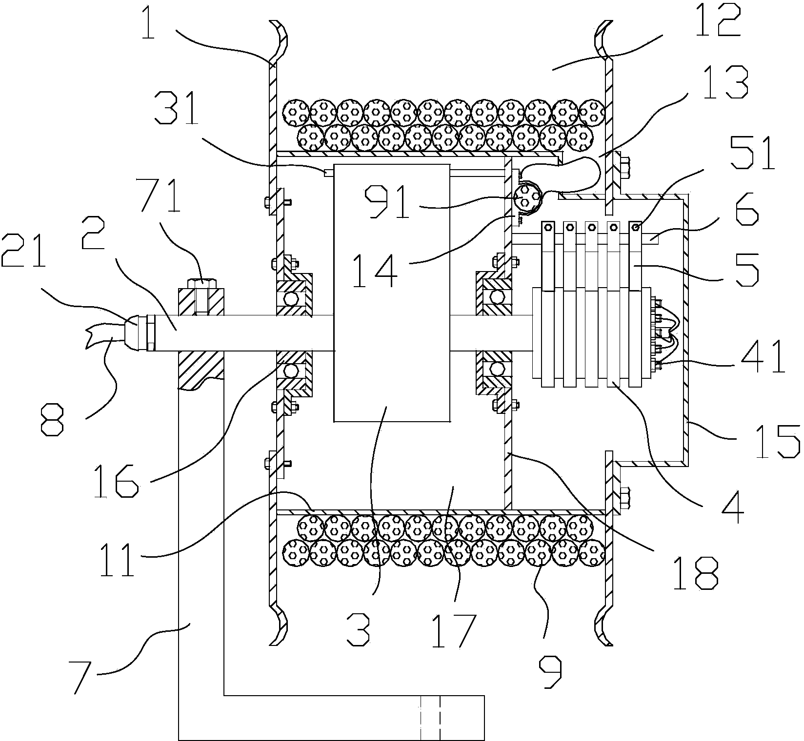
[0013] Such as figure 1 As shown, the bracket 1 is fixed on the mobile device.

[0014] The wire reel 1 is provided with an annular wire groove 12, the cable 9 is wound in the wire groove 12, the hollow mandrel 2 is fixed through the bearing 16 in the middle of the wire reel 1, and there is an annular cavity 17 inside the ring inner wall at the bottom of the wire groove 12 , the cavity 17 is equipped with a scroll spring 3, the inner end of the scroll spring 3 adopts a straight hook type, and is fixed on the mandrel 2 through a card slot embedded in the mandrel 2, and the outer end of the scroll spring 3 adopts a hinged type, Slip on the pull rod 31 that is fixedly connected with the side wall 18 of the wire tray.

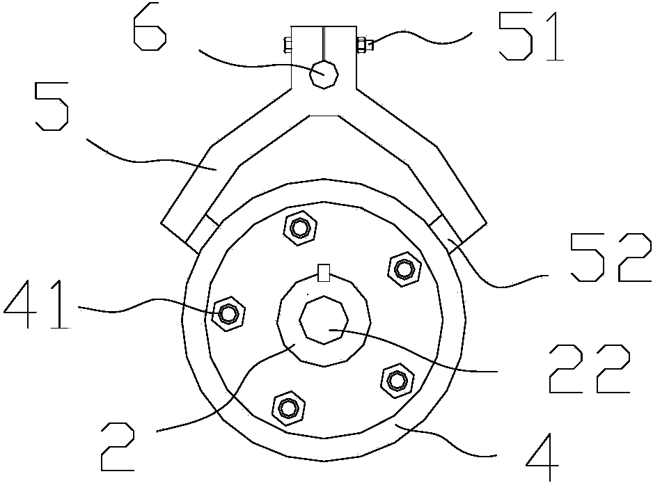
[0015] Both ends of the mandrel 2 extend to the outside of the coil 1 . Wherein, the bracket 7 is provided with a shaft hole for the mandrel 2 to pass through, and one end of the mandrel 2 is fixed on the bracket 7 through the shaft hole, and the upper end of the...


PUM


Abstract

The invention relates to a take-up and pay-off device applied to a mobile device. The take-up and pay-off device applied to the mobile device comprises a wire coil for winding cables and a support. A hollow spindle is arranged in the center of the wire coil, a volute spiral spring is mounted in the cavity inside the wire groove of the wire coil, the inner end of the volute spiral spring is fixed on the spindle, and the outer end of the volute spiral spring is hinged to a pull rod fixedly connected to the wire coil. One end of the spindle is fixed on the support, a collecting ring assembly is fixed at the other end of the spindle, a carbon brush and a carbon brush holder are fixed on the wire coil through a fixing shaft, one end of a cable in the middle of the spindle is electrically connected to the electric appliance part of the mobile device, and the other end of the cable in the middle of the spindle is connected to the collecting ring assembly. A cable wound in the wire groove of the wire coil is electrically connected with the carbon brush holder. The volute spiral spring is used as power for taking up or paying off the cables, electric energy is not consumed, the taking up and the paying off of the cables are flexible, and maintenance is convenient to carry out.

Description

technical field [0001] The invention relates to a cable winding device, in particular to a cable winding device for mobile equipment. Background technique [0002] For some large mobile equipment, the control cabinet is separated from the mobile part, and it is necessary to connect the control cabinet and mobile equipment through cables. For example, in the film stretching production line, the round-trip transportation of steel coil cores and large film rolls at the winding station, and the slitting and transportation of large film rolls are all completed by film transport vehicles. The body of this film transport vehicle is designed separately from the control cabinet. There are quite a lot of power cables and control cables between the car body and the control cabinet to complete the power supply and signal transmission tasks. The cable connection between the car body and the control cabinet often uses cable trenches excavated on the ground to pass the cables in the tank c...

Claims


Application Information

Patent Timeline
Patent Type & Authority Applications(China)
IPC IPC(8): B65H75/42B65H75/44
Inventor 钱立文
Owner ANHUI TONGFENG ELECTRONICS
Why Eureka
Try Eureka