Eccentrically oscillating reduction gear, and method for manufacturing eccentric body shaft

A technology of eccentric swing and manufacturing method, applied in the direction of eccentric shaft, manufacturing tool, furnace type, etc., to achieve the effect of improving qualitative characteristics, prolonging life and improving durability

Active Publication Date: 2014-02-19
SUMITOMO HEAVY IND LTD
View PDF7 Cites 9 Cited by
  • Summary
  • Abstract
  • Description
  • Claims
  • Application Information

AI Technical Summary

Problems solved by technology

[0008] However, in the past, there have been few examples of detailed investigation and research on the mechanism related to the durability of the eccentric body shaft. Therefore, when the eccentric body shaft is manufactured, the actual situation is as follows: only the following steps are carried out. figure 2 , Image 6 General surface hardening treatment shown in Example P of conventional hardening treatment

Method used


Image

  • Eccentrically oscillating reduction gear, and method for manufacturing eccentric body shaft
  • Eccentrically oscillating reduction gear, and method for manufacturing eccentric body shaft
  • Eccentrically oscillating reduction gear, and method for manufacturing eccentric body shaft

Examples


Embodiment Construction

[0030] [Concrete Problems of the Invention and Their Solution Principles]

[0031] The present invention is based on the knowledge of elucidating the mechanism of deterioration (damage or wear) of the eccentric body shaft, which has not been fully verified in the past. The specific problem to be focused on is not known in itself, so before proceeding to the description of the embodiment, first, the specific problem to be focused on in the present invention and the principle of its solution will be described in detail.

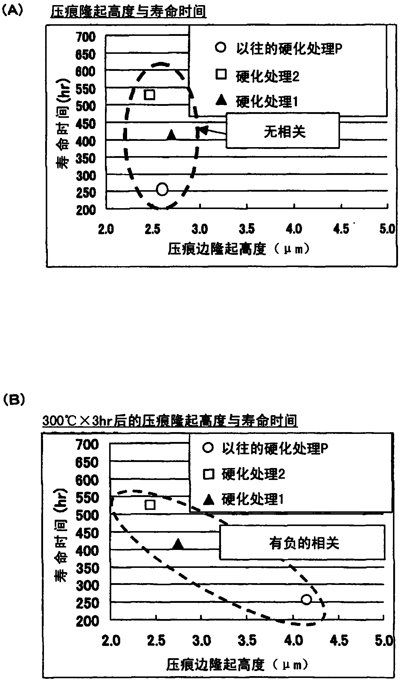
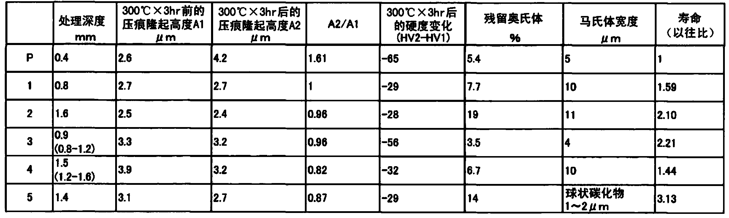
[0032] The inventors presumed the following mechanism as one of the mechanisms (causes) of the deterioration of the eccentric body shaft: image 3 As shown, when foreign matter such as gear wear particles D is mixed between the eccentric body E of the eccentric body shaft and the eccentric body bearing (the rolling element) R, a small indentation M occurs on the surface of the eccentric body E ( figure 1 A→B), the stress is concentrated on the edge of the ind...


PUM

PropertyMeasurementUnit
particle diameteraaaaaaaaaa
widthaaaaaaaaaa
Vickers hardnessaaaaaaaaaa

Abstract

The invention provides an eccentric oscillating type speed reducer and a method for manufacturing an eccentric shaft thereof which may greatly prolong the service life of the eccentric shaft of the eccentric oscillating type speed reducer so as to further improve the durability of the speed reducer. In the eccentric oscillating type speed reducer (12) in which outer gears (24A, 24B) are internally engaged with an inner gear (28) while biasing or crookedly oscillating through the eccentric shaft (20), before applying a thermal load causing a change in the material characteristics of the eccentric shaft (20) to the eccentric shaft (20), a projection resulting from an indentation protrusion test has a height (A1); and after applying the thermal load to the eccentric shaft (20), a projection resulting from the indentation protrusion test has a height (A2); and hardening treatment having such a characteristic that the ratio of A2 to A1 is less than 1.0 is performed on the eccentric shaft.

Description

[0001] This application is a divisional application of an invention patent application with the application number 201110036568.5, the application date is January 31, 2011, and the invention title is "eccentric oscillating reducer and method for manufacturing eccentric body shaft". technical field [0002] The invention relates to an eccentric oscillating reducer and a manufacturing method thereof. [0003] This application claims priority based on Japanese Patent Application No. 2010-022575 filed on February 3, 2010. The entire content of this application is used in this specification by reference. Background technique [0004] Patent Document 1 discloses an eccentric oscillating speed reducer. This speed reducer includes: an external gear; an eccentric body shaft having an eccentric body; an eccentric body bearing disposed between the external gear and the eccentric body; and an internal gear. [0005] In such a speed reducer, the eccentric body shaft is rotated by the r...

Claims


Application Information

Patent Timeline
Patent Type & Authority Applications(China)
IPC IPC(8): F16C3/18C21D7/12C21D9/30
CPCF16H2001/323
Inventor 石川哲三永濑纯也
Owner SUMITOMO HEAVY IND LTD
Why Eureka
Try Eureka