
Single-water-path ceramic valve element structure

A ceramic spool and single waterway technology, which is applied in sliding valves, valve devices, engine components, etc., can solve the problems of human body injury, spool easy to leak, and poor water safety of the spool, so as to reduce the force strength requirements, The effect of improving water safety and increasing service life

Active Publication Date: 2014-02-19
XIAMEN LOTA INT CO LTD
View PDF6 Cites 7 Cited by
  • Summary
  • Abstract
  • Description
  • Claims
  • Application Information

AI Technical Summary

Problems solved by technology

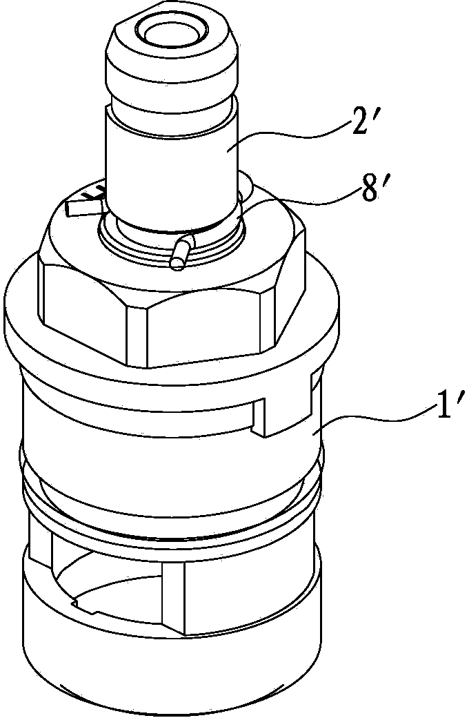
[0005] 1. The design of the valve stem rotation angle limit structure is not good, because the valve core uses the valve stem 2' symmetrical plane 22' to cooperate with the stressed metal ring 7' in the special-shaped inner cavity of the valve housing 1' to form a rotation angle The limit structure of the force-bearing metal ring 7', the outer edge of the groove 71', and the shear force of the limit block 11' of the valve casing 1' are relatively concentrated. Shell 2' special-shaped inner cavity is easily damaged, that is, the strength of the valve core to withstand torque is low, which in turn affects the service life of the valve core
[0006] 2. It is laborious to operate the ceramic piece by the valve stem, because the lower end of the valve stem 2' passes through the base 3' and relies on the cooperation of the protrusion 21' at the lower end and the groove 41' in the center of the upper ceramic piece 4' to realize the linkage between the two , because the valve stem 2' drives the upper ceramic piece 4' to rotate, the force arm is relatively short, so the operation of the valve stem 2' is relatively laborious, that is, the strength of the valve core to withstand the torque is low
[0007] 3. The cost of the valve stem is high, and the water safety of the valve core is poor. Since the lower part of the valve stem 2' is placed in the water passage area in the inner cavity of the valve housing 1', see Figure 4 The position of the middle water level line W', and the valve stem 2' is mostly made of metal copper, which is expensive and contains lead, which is harmful to the human body
[0008] 4. The wear-resistant structure is complicated. Since the wear-resistant position of the valve core, that is, the place between the lower part of the valve stem 2' and the base 3' is made of metal material, it is not conducive to wear-resistant, and it is necessary to increase the wear-resistant gasket 6', so it increases virtually. The structural components of the spool are removed, increasing the complexity of the mechanism
[0009] 5. The spool is prone to water leakage at low pressure. Since the low-pressure support ring 91' at the bottom of the valve housing 1' is set on the outer edge of the sealing ring 9', the sealing ring 9' is easy to deform inward when the water pressure is low. The sealing ring 9' and the Water leakage is prone to occur between valve shells 1'

Method used


Image

  • Single-water-path ceramic valve element structure
  • Single-water-path ceramic valve element structure
  • Single-water-path ceramic valve element structure

Examples


Embodiment approach

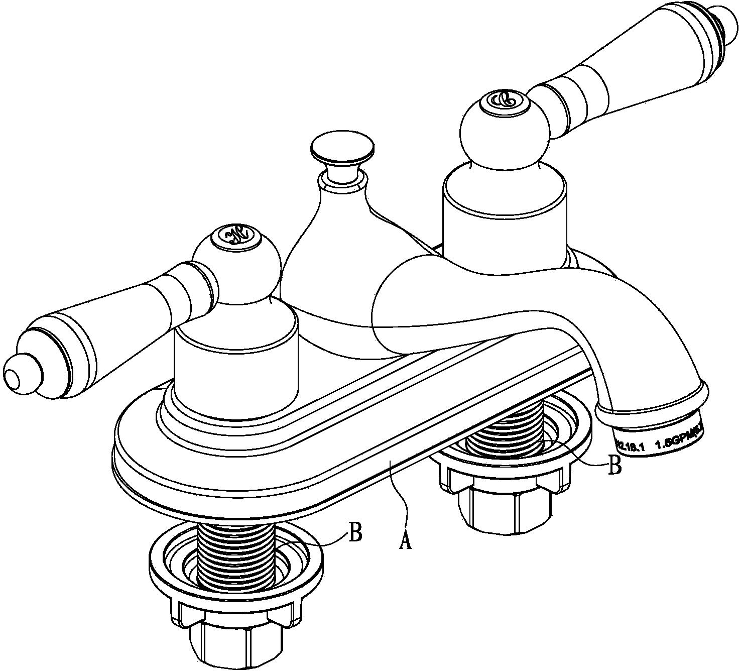
[0038] like Figure 7 to Figure 13 and cooperate figure 1 As shown, the present invention discloses a single-water channel ceramic valve core structure, which is respectively assembled in the cold and hot water inlet pipes B of the faucet A; it includes a valve housing 1, a valve stem 2, a base 3, a The upper ceramic sheet 4, the lower ceramic sheet 5 and the sealing ring 6; an arc-shaped groove 11 is formed on the side wall of the upper part of the valve housing 1, and a water outlet 12 is formed on the lower side wall; the base 3 is an upper chamber 31 with no communication The cylinder sleeve of the lower chamber 32 has a matching hole 33 corresponding to the arc groove 11 of the valve casing 1 on its upper part; and a horizontal assembly hole 21 is provided on the lower part of the valve stem 2, and the base 3 is sealed and assembled on the valve body from bottom to top. In the casing 1, the valve stem 2 passes through the valve casing 1 from top to bottom and is placed ...


PUM


Abstract

The invention discloses a single-water-path ceramic valve element structure. The single-water-path ceramic valve element structure comprises a valve shell, a pin, a valve rod, a base, an upper ceramic piece, a lower ceramic piece and a seal ring. An arc-shaped groove is formed in the lateral wall of the upper portion of the valve shell, the base is a column sleeve provided with an upper chamber and a lower chamber, the upper chamber is not communicated with the lower chamber and a matching hole is formed in the position, corresponding to the arc-shaped groove of the valve shell, of the upper portion of the column sleeve. The base is assembled inside the valve shell in a sealed mode from bottom to top, the valve rod penetrates through the valve shell from top to bottom to stretch into the upper chamber of the base, the pin transversely penetrates through the arc-shaped groove of the valve shell and the matching hole of the base to be connected with the lower portion of the valve rod together. The upper ceramic piece, the lower ceramic piece and the seal ring are sequentially matched inside the valve shell, and the periphery of the upper ceramic piece and the bottom of the base are matched together. The valve rod is provided with a limiting structure of a rotation angle, and the limiting structure is formed by the pin and the arc-shaped groove in the lateral wall of the valve shell so that the valve element can bear larger torque and the service life of a valve element can be prolonged; part of the valve rod is replaced by the base, so that overflow safety is improved.

Description

technical field [0001] The invention relates to a valve core structure of a water outlet device, in particular to a single water channel ceramic valve core structure. Background technique [0002] The service life of the faucet is mainly determined by the life of the spool inside the faucet, and the rationality of the structure design of the spool is also the key to directly determine the service life of the spool. The single water channel ceramic spool is mainly used in the cold and hot water pipelines of the double handle faucet. [0003] like Figure 1 to Figure 6 As shown, the current common single water channel ceramic valve core, its structure includes: valve housing 1', metal valve stem 2', base 3', upper ceramic piece 4', lower ceramic piece 5', valve stem 2' through the sleeve The wear-resistant gasket 6' and the stressed metal ring 7' extend from the lower part of the valve housing 1' and are placed in the valve housing 1', and cooperate with the valve stem sealin...

Claims


Application Information

Patent Timeline
Patent Type & Authority Applications(China)
IPC IPC(8): F16K3/08F16K3/30
CPCF16K3/08F16K3/314F16K3/36
Inventor 叶立明周建平白双林张潇潇
Owner XIAMEN LOTA INT CO LTD
Learn More