Pressurization visual combustion test device of combustor of gas turbine
A technology of gas turbine and combustion test, applied in the direction of measuring device, engine test, machine/structural component test, etc., to achieve the effect of cheap material, good perspective and simple processing technology
- Summary
- Abstract
- Description
- Claims
- Application Information
AI Technical Summary
Problems solved by technology
Method used
Image

Examples
specific Embodiment approach 1
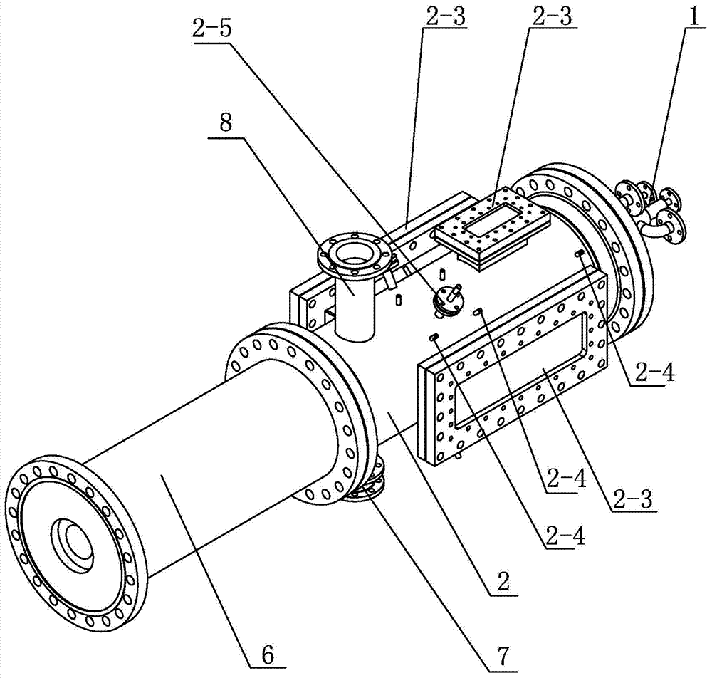
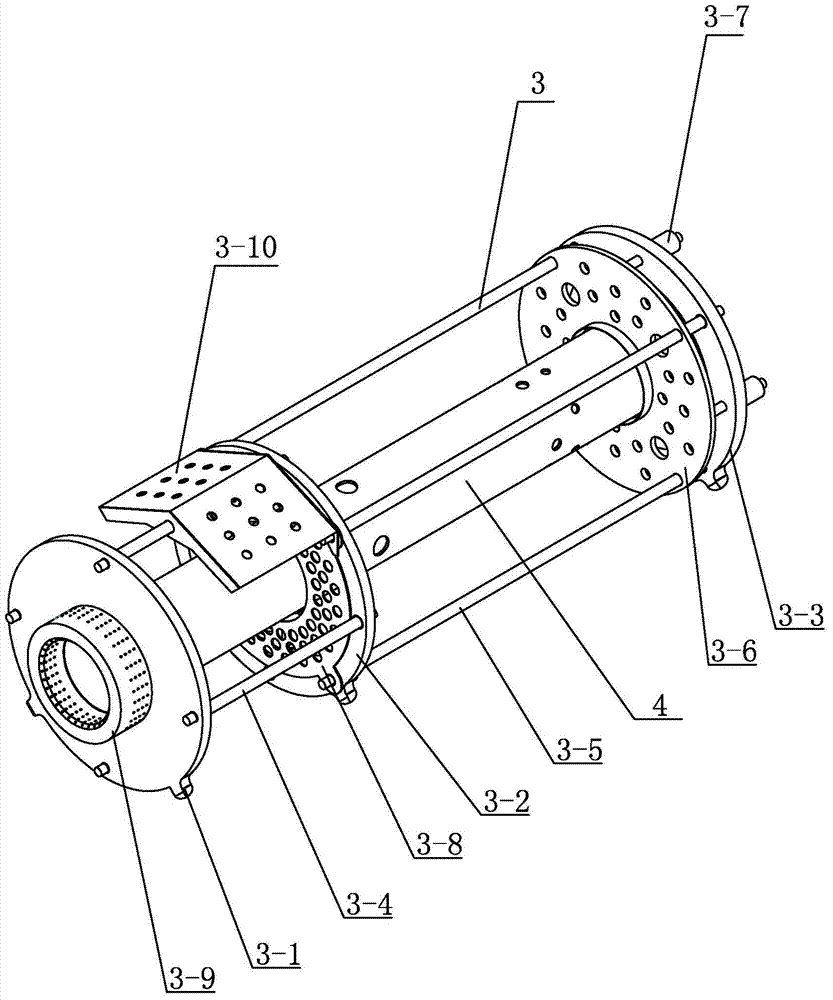
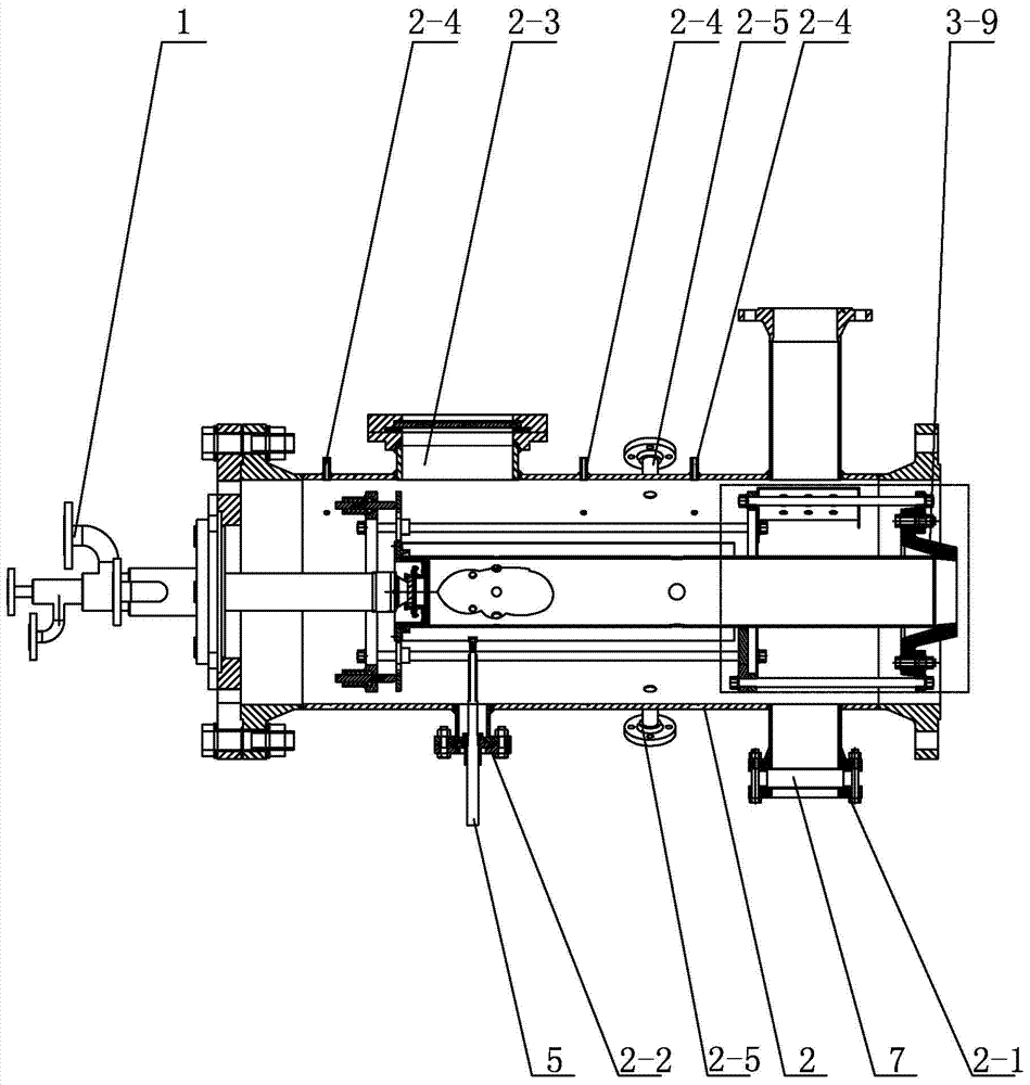
[0007] Specific implementation mode one: combine figure 1 , figure 2 with image 3 To illustrate this embodiment, the gas turbine combustor pressurized visual combustion test device described in this embodiment includes a single nozzle installation flange cover 1, a pressure-bearing casing 2, an elastic bracket assembly 3, a quartz glass flame tube 4, and a telescopic igniter 5. The high temperature measurement section 6 and the explosion-proof mechanism 7, the pressure casing 2 is set horizontally, the single nozzle installation flange cover 1 is installed on the end face of one end of the pressure casing 2, the pressure casing 2 is connected with the high temperature measurement section 6, The explosion-proof mechanism 7 is installed on the explosion-proof clamping flange 2-1 on the lower surface of the pressure-bearing casing 2, the elastic bracket assembly 3 is inserted in the pressure-bearing casing 2, and the glass flame tube 4 is adapted to be inserted into the elasti...
specific Embodiment approach 2
[0009] Specific implementation mode two: combination figure 1 with image 3 Describe this embodiment, the gas turbine combustor pressurized visual combustion test device described in this embodiment is respectively provided with a viewing window 2-3 on the upper surface and two sides of the pressure casing 2, and the upper surface of the pressure casing 2 is Three rows of temperature and pressure measuring points 2-4 are arranged at equal intervals on the upper surface, and two secondary diluent interface flanges 2-5 are respectively arranged on the upper surface and the lower surface of the pressure-bearing casing 2.
[0010] In this embodiment, after the compressed air enters from the inlet flange on the pressure-bearing casing 2, the air state parameters at the inlet of the tester are measured through the temperature and pressure measuring points 2-4, and then the four secondary diluent interface flanges 2-5 are downstream The compressed air is mixed with the secondary dil...
specific Embodiment approach 3
[0012] Specific Embodiment 3: This embodiment is described in conjunction with 1. Each viewing window 2-3 of the gas turbine combustor pressurized visual combustion test device in this embodiment is a viewing window 2-3 made of synthetic adaptive glass.
[0013] The technical effect of this embodiment is: so set, the peep window 2-3 can not only pass through the far ultraviolet spectrum, but also can pass through the visible light and near-infrared spectrum, can work at a temperature above 950°C for a long time, and realize it at a temperature above 1200°C Working at the maximum cycle, the three peep windows 2-3 are used in conjunction with each other, so that the combustion flame in the quartz glass flame tube 4 can be observed by the experimenter with the naked eye, and can cooperate with the combustion optical measurement system to measure the flame in the quartz glass flame tube 4 form and structure. Other components and connections are the same as those in the second embo...
PUM
 Abstract
Description
Claims
Application Information
 - Generate Ideas
- Intellectual Property
- Life Sciences
- Materials
- Tech Scout
- Unparalleled Data Quality
- Higher Quality Content
- 60% Fewer Hallucinations
Browse by: Latest US Patents, China's latest patents, Technical Efficacy Thesaurus, Application Domain, Technology Topic, Popular Technical Reports.
© 2025 PatSnap. All rights reserved.Legal|Privacy policy|Modern Slavery Act Transparency Statement|Sitemap|About US| Contact US: help@patsnap.com