
A Synchronous Sampling Control Circuit of Multiple Signals Based on FPGA

A multi-channel signal, synchronous sampling technology, applied in the direction of program control, computer control, general control system, etc., to achieve the effect of strong practicability

Active Publication Date: 2017-06-16
GUANGXI UNIV
View PDF4 Cites 2 Cited by
  • Summary
  • Abstract
  • Description
  • Claims
  • Application Information

AI Technical Summary

Problems solved by technology

[0003] The purpose of the present invention is to solve the problem of synchronous sampling of multi-channel non-analog signals, thereby proposing a multi-channel signal synchronous sampling control circuit based on FPGA

Method used


Image

  • A Synchronous Sampling Control Circuit of Multiple Signals Based on FPGA
  • A Synchronous Sampling Control Circuit of Multiple Signals Based on FPGA
  • A Synchronous Sampling Control Circuit of Multiple Signals Based on FPGA

Examples


Embodiment Construction

[0022] The present invention will be further described below in conjunction with the accompanying drawings.

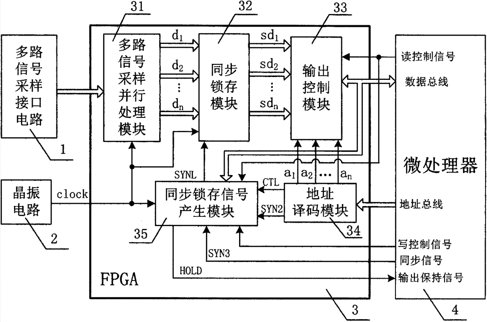
[0023] Such as figure 1 Shown is an overall block diagram of the technical solution of an FPGA-based multi-channel signal synchronous sampling control circuit. The number of signal channels input by the multi-channel signal sampling interface circuit 1 can be any digital pulse signal greater than or equal to 2 channels. Taking the case where the number of signal channels input by the multi-channel signal sampling interface circuit 1 is three digital pulse signals, the design is as follows: Figure 4 A specific embodiment of a multi-channel signal synchronous sampling control circuit based on FPGA shown, this control circuit at least includes three-way signal sampling interface circuit 1, crystal oscillator circuit 2, FPGA chip 3 and microprocessor 4; Said FPGA The chip 3 at least includes a three-way signal sampling parallel processing module 31 , a synchronous latch ...


PUM


Abstract

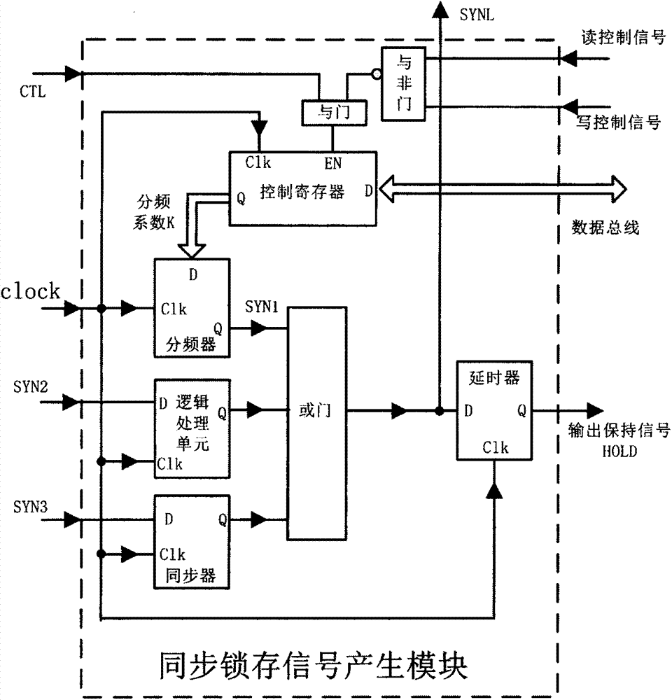
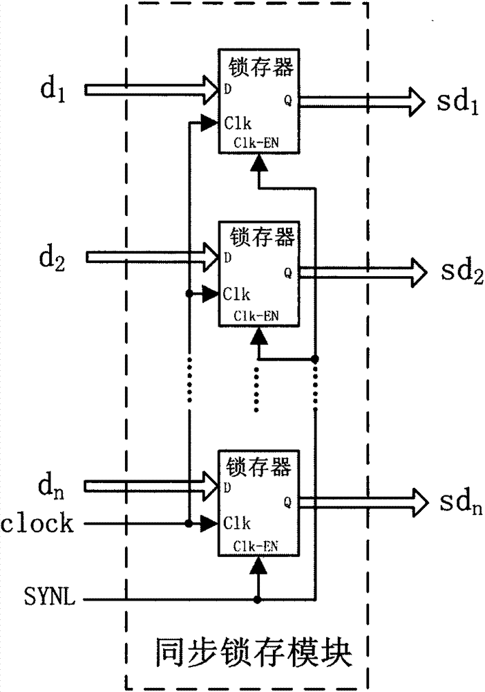
The invention discloses an FPGA-based multi-channel signal synchronous sampling control circuit, which at least includes a multi-channel signal sampling interface circuit, a crystal oscillator circuit, an FPGA chip and a microprocessor; the FPGA chip at least includes a multi-channel signal sampling parallel processing module, a synchronous lock Storage module, output control module, address decoding module and synchronous latch signal generation module; the synchronous latch signal SYNL output by the synchronous latch signal generation module controls the synchronous latch module to sample multiple signals and process the multi-channel data output by the module in parallel The synchronous latch keeps the multi-channel data output by the multi-channel signal sampling parallel processing module unchanged at the same time, and ensures the synchronization between the data read by the microprocessor from the FPGA chip one by one. The invention is suitable for a control system requiring synchronous sampling of multi-channel signals, especially for a control system for synchronous sampling of multi-channel pulse signals or multi-channel digital signals, which is flexible, convenient and practical.

Description

technical field [0001] The invention relates to the technical field of signal acquisition and transmission, in particular to an FPGA-based multi-channel signal synchronous sampling control circuit. Background technique [0002] In modern control systems, signal acquisition systems have been widely used in electronic measurement, communication, radar, aerospace, industrial control and other fields. Signals can be classified into analog and digital signals. To collect the analog signal, it is necessary to use an analog-to-digital converter (ADC) for collection. In the prior art, a great deal of research has been done on synchronous sampling of multiple analog signals. Chinese Patent Document Nos. ZL200810240063.9, ZL201010577253.7, ZL201310087071.5, ZL200720311326.1, etc. are only inventions and designs on how to sample multiple analog signals synchronously, but digital pulse signals with some non-analog signals cannot be compared with analog signals. The ADC is used for sy...

Claims


Application Information

Patent Timeline
Patent Type & Authority Patents(China)
IPC IPC(8): G05B19/042
Inventor 潘海鸿韦庆情陈琳黄炳琼
Owner GUANGXI UNIV
Learn More