Efficient cooling transformer

A transformer and high-efficiency technology, which is applied in the field of transformers, can solve the problems of poor heat dissipation effect on the surface of heat dissipation monomers, slow heat dissipation circulation speed of transformer oil, and small gap between cooling elements, so as to improve heat dissipation effect, improve cooling effect, and cool down effect Good results

Active Publication Date: 2014-02-19
ZHEJIANG BOTHWELL ELECTRIC
View PDF7 Cites 10 Cited by
  • Summary
  • Abstract
  • Description
  • Claims
  • Application Information

AI Technical Summary

Problems solved by technology

[0002] The current transformers are all equipped with transformer oil. In order to reduce the temperature of the transformer oil, a cooling device is installed to reduce the temperature of the transformer oil. The existing cooling device is to install a flat cooling box on the side of the transformer oil tank, and insert multiple A flat cooling unit, this setting increases the heat dissipation area of ​​the transformer oil to enhance the heat dissipation effect, but the gaps between the multiple cooling units are small, the air does not circulate, and the heat is easy to accumulate in the gaps, resulting in heat dissipation. The heat dissipation effect of the body surface becomes worse; and the heat dissipation device is made of metal, the manufacturing cost is high, the structure is complicated, the installation is difficult, the heat dissipation cycle speed of the transformer oil is slow, and the transformer is easily damaged due to the high temperature of the transformer oil

Method used


Image

  • Efficient cooling transformer
  • Efficient cooling transformer
  • Efficient cooling transformer

Examples


Embodiment Construction

[0012] In order to enable those skilled in the art to better understand the solutions of the present invention, the technical solutions in the embodiments of the present invention will be clearly and completely described below in conjunction with the drawings in the embodiments of the present invention.

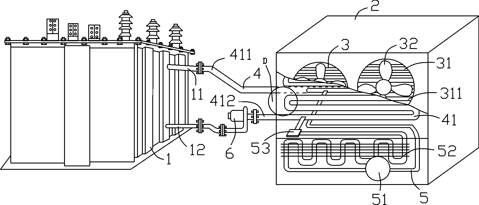
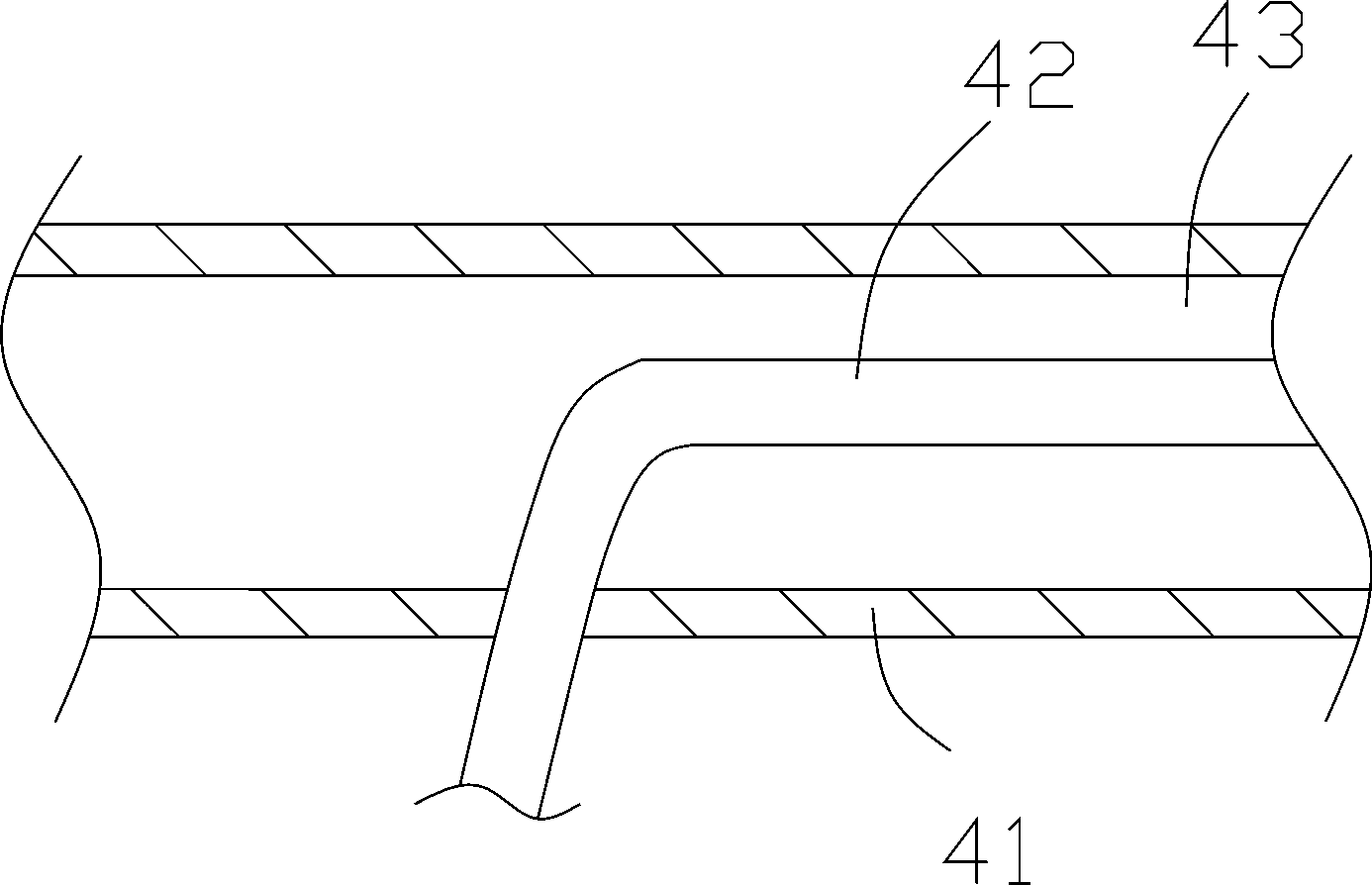
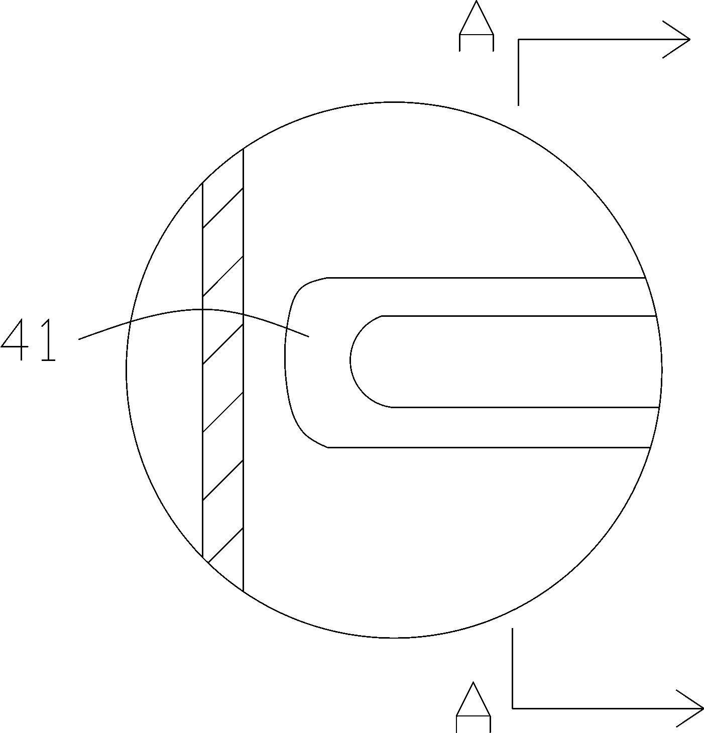
[0013] Such as Figure 1-4 As shown, a high-efficiency cooling transformer includes an oil tank 1 and a cooling box 2 connected to the oil tank 1. The upper end of the oil tank 1 is provided with a first connecting pipe 11, and the lower end of the oil tank 1 is provided with a second connecting pipe 12. Inside the cooling box 2 A mounting frame is provided; the upper end and the lower end of the mounting frame are respectively fixed on the upper end and the lower end of the cooling box 2, and a cooling device 4 is fixed on the mounting frame by bolts. The mounting frame is provided to make the installation of the cooling device more stable and firm.

[0014] Specifically, th...


PUM


Abstract

The invention discloses an efficient cooling transformer which comprises an oil tank and a cooling tank. A first connecting pipe is arranged at the upper end of the oil tank, the lower end of the oil tank is provided with a second connecting pipe, the cooling tank is provided with a ventilation device, and an installation frame is arranged in the cooling tank. A cooling device is fixed onto the installation frame through bolts, the cooling device comprises a cooling pipe and an inner evaporation pipe, the inner evaporation pipe is sleeved with the cooling pipe, a heat absorption working medium flows in the inner evaporation pipe, and a gap allowing transformer oil to circulate is formed between the cooling pipe and the inner evaporation pipe. The cooling pipe comprises an oil inlet end and an oil outlet end, the oil inlet end stretches out of the cooling tank to be connected with the first connecting pipe of the oil tank in a flanged mode, the oil outlet end stretches out of the cooling tank to be connected with an oil pump, and the oil pump is connected with the second connecting pipe of the oil tank in a flanged mode. The inner evaporation pipe is connected with a refrigeration mechanism, the refrigeration mechanism comprises a compressor, a continuous-U-shaped condensation pipe and a throttling valve, and the ventilation device comprises a through hole formed in the inner wall of the cooling tank and a fan arranged in the through hole. The efficient cooling transformer is good in heat dissipation effect and high in heat dissipation circulation speed.

Description

technical field [0001] The invention relates to the field of transformers, in particular to a high-efficiency cooling transformer. Background technique [0002] The current transformers are equipped with transformer oil. In order to reduce the temperature of the transformer oil, a cooling device is installed to reduce the temperature of the transformer oil. The existing cooling device is to install a flat cooling box on the side of the transformer oil tank, and insert multiple A flat cooling unit, this setting increases the heat dissipation area of ​​the transformer oil to enhance the heat dissipation effect, but the gaps between the multiple cooling units are small, the air does not circulate, and the heat is easy to accumulate in the gaps, resulting in heat dissipation. The heat dissipation effect of the body surface becomes worse; and the heat dissipation devices are all made of metal, the manufacturing cost is high, the structure is complicated, the installation is diffi...

Claims


Application Information

Patent Timeline
Patent Type & Authority Applications(China)
IPC IPC(8): H01F27/08H01F27/18
Inventor 叶仁富
Owner ZHEJIANG BOTHWELL ELECTRIC
Why Eureka
Try Eureka