Device for measuring flow and wind velocity of stator and rotor of large power generator

A technology for measuring rotor flow and wind speed. It is used in electromechanical devices, electrical components, and electric components. It can solve problems such as difficulty in measuring flow and wind speed, and achieve the effects of avoiding experimental costs, stabilizing output speed, and improving reliability.

Active Publication Date: 2014-02-19
BEIJING JIAOTONG UNIV
View PDF2 Cites 1 Cited by
  • Summary
  • Abstract
  • Description
  • Claims
  • Application Information

AI Technical Summary

Problems solved by technology

Due to the space limitation of the generator and the influence of the complex electromagnetic field in the motor on the measurement, it is difficult to test the flow and wind speed in the stator, rotor and air gap of a large generator in an actual motor

Method used


Image

  • Device for measuring flow and wind velocity of stator and rotor of large power generator
  • Device for measuring flow and wind velocity of stator and rotor of large power generator
  • Device for measuring flow and wind velocity of stator and rotor of large power generator

Examples


Embodiment Construction

[0012] Combine below Figure 1-3 , the present invention will be further described by specific embodiment;

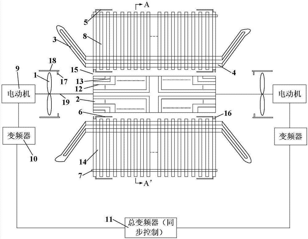
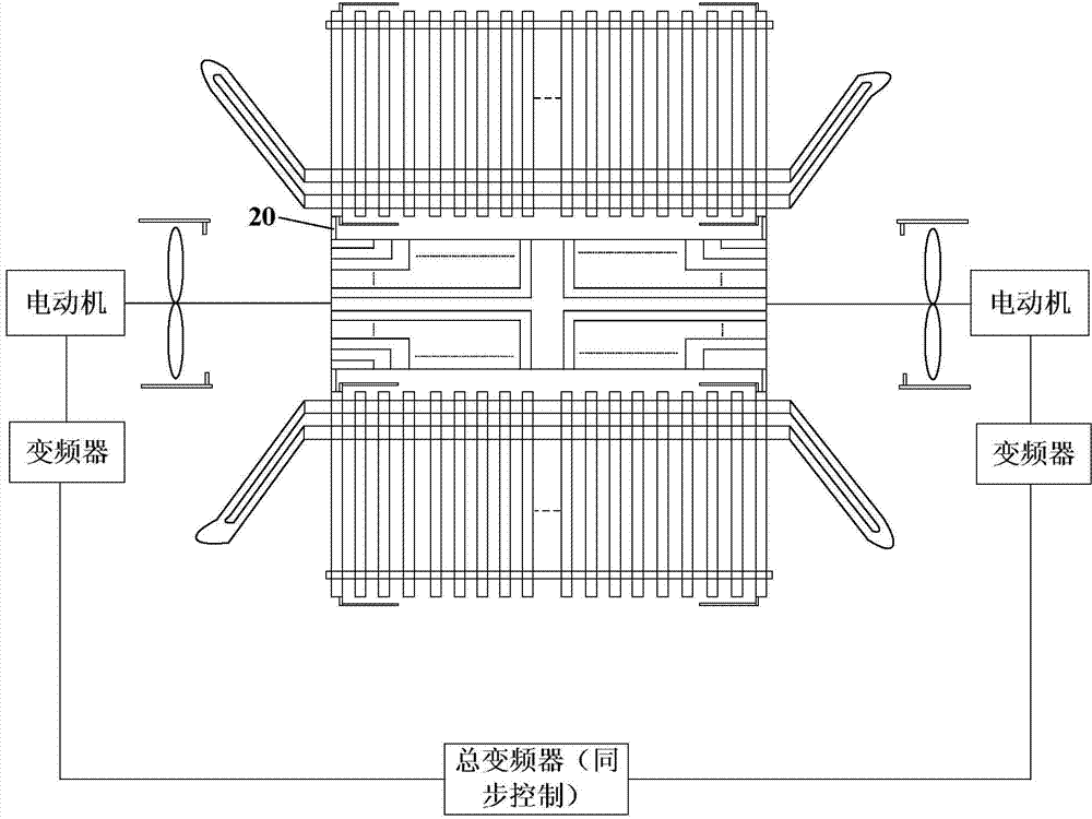
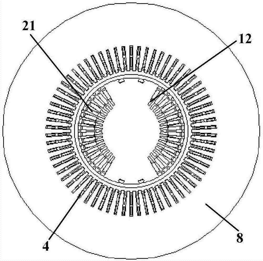
[0013] see figure 1 with image 3 , The large-scale generator stator and rotor flow wind speed measuring device of the present invention, the main body is a simulated turbo generator stator and rotor simulation device. The rotor 2 with auxiliary grooves is made into a solid body of wooden structure, and the solid body of wooden structure is provided with auxiliary groove ventilation grooves 12, rotor radial ventilation grooves 13 and rotor grooves 21 that are the same as those of the turbine generator rotor. Copper windings are embedded in the rotor slots 21 .

[0014] The stator side adopts the principle similar to that of the turbogenerator stator, and is provided with stator end windings 3 and stator straight section windings 4 . These stator windings are non-copper windings and consist of solid wood overwrapped insulation. The stator core 8 is also made of wood...


PUM


Abstract

The invention discloses a device for measuring the flow and wind velocity of a stator and a rotor of a large power generator, and belongs to the electrical field. The problem that due to limitation of space of the power generator and influences of the complex electromagnetic field in a motor on measurement, the flow and wind velocity of the stator and the rotor of the large power generator and the flow and wind velocity in an air gap between the stator and the rotor of the large power generator are very difficult to measure in an actual motor and other problems are solved through the device. A rotor solid body provided with an auxiliary groove ventilating duct, a radial ventilating duct and a rotor groove is arranged, the auxiliary groove ventilating duct, the radial ventilating duct and the rotor groove are the same as those of a rotor of a turbonator, and a wooden stator core and stator windings are arranged on a stator side. Forward extending type wind velocity measuring sensors are arranged at the back portion of a stator yoke, in the air gap between the stator and the rotor and in the position of an air deflector of a tube-axial fan respectively, and the wind velocity in the device can be monitored. By synchronously adjusting output frequencies of two frequency converters in the whole measuring device, the aim of adjusting the rotating speed of an electric motor is achieved. The flow and flow velocity of the stator and the rotor of the large power generator and the flow and flow velocity in the air gap between the stator and the rotor of the large power generator can be accurately measured through the device, high experimental expenses are prevented, and the device has the advantages of being accurate in measurement, easy to obtain and the like.

Description

technical field [0001] The invention relates to a large-scale generator stator and rotor flow wind speed measuring device, which belongs to the electric field. Background technique [0002] At present, engineering designers are very concerned about the flow rate in the stator, rotor and air gap of large generators above 100 MW, their respective proportions to the total flow, and the wind speed in the stator, rotor and air gap. Due to the limited space of the generator and the influence of the complex electromagnetic field in the motor on the measurement, it is difficult to test the flow and wind speed in the stator, rotor and air gap of a large generator in an actual motor. Contents of the invention [0003] In order to accurately determine the wind speed and air volume in the stator, rotor and air gap of the motor and their proportions to the total air volume, a new measuring device is proposed. [0004] The technical scheme that the present invention proposes is: [00...

Claims


Application Information

Patent Timeline
Patent Type & Authority Applications(China)
IPC IPC(8): H02K11/00H02K11/20H02K11/21
Inventor 李伟力韩继超王立坤焦晓霞
Owner BEIJING JIAOTONG UNIV
Why Eureka
Try Eureka