High-speed array chip mounter

An array type, placement machine technology, applied in electrical components, electrical components and other directions, can solve the problems of multi-time, overall placement efficiency reduction, waste, etc., to achieve high adjustment accuracy, improve debugging speed, and improve production efficiency. Effect

Active Publication Date: 2014-02-19
浙江华企正邦自动化科技有限公司
View PDF4 Cites 7 Cited by
  • Summary
  • Abstract
  • Description
  • Claims
  • Application Information

AI Technical Summary

Problems solved by technology

The placement head is mainly composed of the placement head base, the nozzle rod and the nozzle. Especially in the products of the LED industry, the length of the circuit board is 10cm-150cm, and more than 100 LED illuminants will be arranged on the PCB. The distance between the LED illuminants on each product is different, so that the placement head can be slid left and right, and the distance between the placement heads can be adjusted according to the distance between the LEDs on the PCB, so as to achieve simultaneous suction and placement , so the distance between the two placement heads is very short. When adjusting, it must be adjusted and locked one by one from the left or right. The existing locking mechanism is not set on the front of the placement head base. When the initial adjustment fails to achieve the accuracy of the mounting head, it needs to be readjusted. It is necessary to remove the rear mounting head from the adjusted one before putting it into the tool for adjustment. After the adjustment, the removed one must be readjusted and locked. , in addition, the sliding of the existing placement head is realized by the card slot, which cannot achieve the accuracy of sliding
[0003] At the same time, the feeder is used corresponding to the placement head, and the adjustment needs to be calibrated with special tools. If one of them does not match, it needs to be adjusted repeatedly with special tools, which wastes a lot of time
Since the length of the circuit board reaches more than 50cm, there is no such a large mold on the market to produce circuit board products. It can only be produced by "V-pit machine", so that the appearance and size of each circuit board cannot be consistent. The circuit boards on the pallet cannot be placed accurately when they are fed into the machine
In addition, the existing placement machine uses a single-side feeding table and a belt-type track to send the circuit board into the placement machine for placement. The single-side feeding table mounting process takes a certain amount of time, and the operator is idle and waiting. state, the second circuit board can be placed and sent to the placement machine for placement after the placement is completed and the circuit board is removed.
The other belt-type rail feeding works in the same way. The second circuit board can only be sent to the second circuit board after the first circuit board is pasted. The belt-type rail feeding is used on the array mounter, and the length of the circuit board is more than 50cm. When the specifications are inconsistent, the placement will not be on the expected coordinates, because the consistency of each circuit board sent into the placement cannot be guaranteed, so the overall placement efficiency will be reduced, the labor of the staff will not be fully utilized, and the array will be lost. The significance of high-speed and efficient placement of the placement machine itself

Method used


Image

  • High-speed array chip mounter
  • High-speed array chip mounter
  • High-speed array chip mounter

Examples


Embodiment Construction

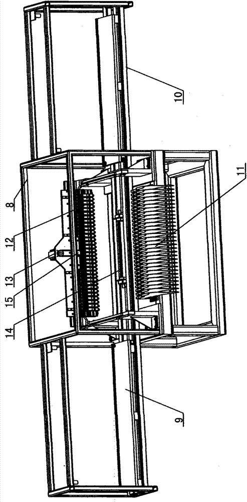
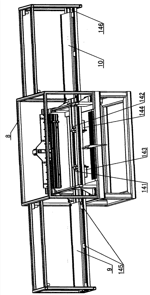
[0033] like figure 1 , Figure 4 As shown, the high-speed array placement machine described in the embodiment of the present invention includes a placement frame 8, and a left pallet 9 and a right pallet 10 are laid horizontally on both sides of the chip frame 8 respectively, located on the left Camera III6 is installed above the connecting position of pallet platform 9 and placement frame 8, and camera IV7 is installed on the frame above the outer end of pallet platform 9 on the left side, and the diagonal reference point of the circuit board is picked up diagonally downwards (can be opposite to Find a pad at the corner) After aligning with the cross coordinate line of the camera, fix the position of the circuit board and send it to the machine for placement, so as to ensure that the position of each circuit board sent into the machine is consistent and achieve accurate placement;

[0034] Two cameras are arranged at the position where the right supply pallet 10 meets the mo...


PUM


Abstract

The invention relates to a high-speed array chip mounter. The chip mounter comprises a chip mounter rack, wherein a left board feeding platform and a right board feeding platform are laid horizontally on the two sides of the chip mounter rack respectively, a forward looking camera is arranged on the front side of the right board feeding platform, an up looking camera is arranged on the upper surface of the right board feeding platform, array mounting heads are arranged on a beam in the chip mounter rack, and a down looking camera is installed at the bottoms of the array mounting heads. An up-down movement mechanism is arranged on the back faces of the array mounting heads, a board feeding mechanism is horizontally laid between the left board feeding platform and the right board feeding platform, and array feeders are installed on one side of the chip mount rack. The high-speed array chip mounter has the advantages that the thirty array mounting heads are adopted for synchronously moving to the corresponding thirty feeders, meanwhile, the cameras are arranged in the area of the left board feeding platform and the area of the right board feeding platform, the cross line on a displayer plays a role in positioning circuit boards, it can be ensured that the fed circuit boards to be mounted are uniform in position, staff are used sufficiently, and high-speed high-efficiency production is achieved.

Description

technical field [0001] The invention relates to the field of placement machines, in particular to a high-speed array placement machine. Background technique [0002] The placement machine is configured after the dispensing machine or screen printing machine. It is a device that accurately places surface mount components on the PCB pads by moving the placement head. It is divided into manual and fully automatic. Among them, the automatic placement machine is used to realize high-speed, high-precision, fully automatic placement of components, and is the most critical and complex equipment in the entire SMT production. In order to achieve high-speed and efficient placement, 10 or more placement heads will be installed on an existing machine, which is called an array placement machine. The placement head is mainly composed of the placement head base, the nozzle rod and the nozzle. Especially in the products of the LED industry, the length of the circuit board is 10cm-150cm, and...

Claims


Application Information

Patent Timeline
Patent Type & Authority Applications(China)
IPC IPC(8): H05K13/04
Inventor 梁文灿
Owner 浙江华企正邦自动化科技有限公司
Why Eureka
Try Eureka