trickle dispenser

A dispenser and trickle technology, applied in the field of trickle dispensers, can solve the problems of incomplete dispensing of drops, atomization of fluid products, etc.

Active Publication Date: 2016-02-17
APTAR FRANCE SAS
View PDF9 Cites 0 Cited by
  • Summary
  • Abstract
  • Description
  • Claims
  • Application Information

AI Technical Summary

Problems solved by technology

If the user omits this pre-step, there is a risk of dispensing incomplete drops or even aerosolizing the fluid since the fluid chamber may be partially filled with air

Method used


Image

  • trickle dispenser
  • trickle dispenser
  • trickle dispenser

Examples


Embodiment Construction

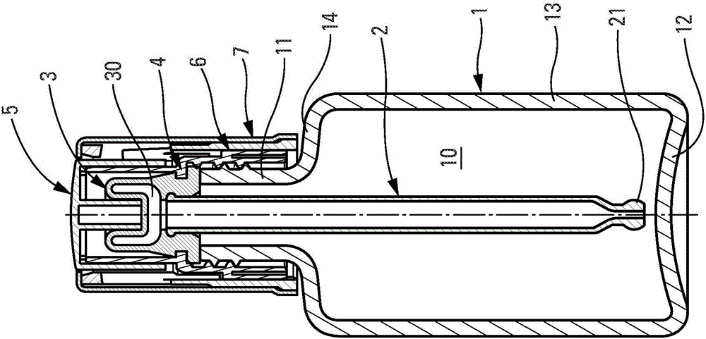
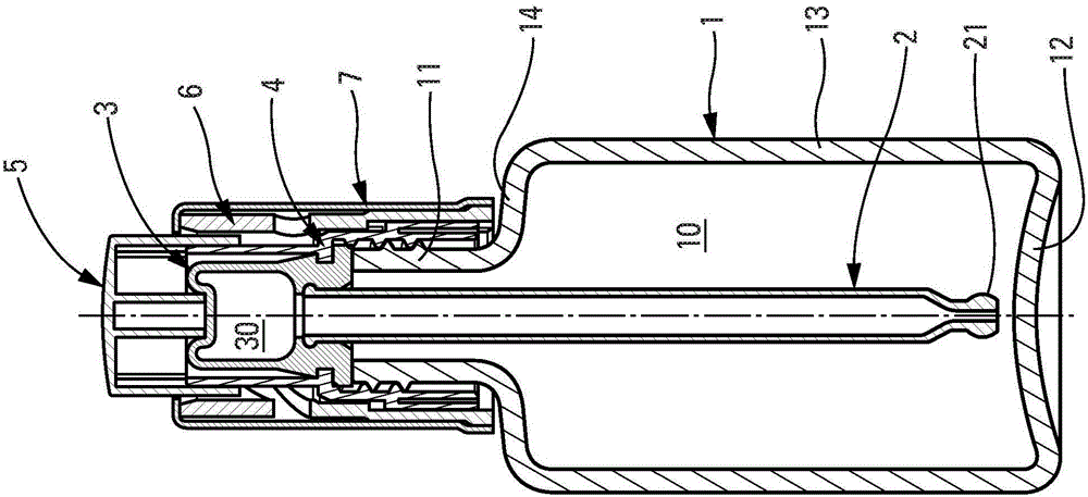
[0024] First refer to Figure 1a and 1b The overall structure of a trickle dispenser according to a non-limiting embodiment of the present invention will be described. The trickle dispenser includes seven constituent elements, namely a fluid product reservoir 1 , a tube 2 , a flexible member 3 , a fixing ring 4 , a pressing piece 5 , a sleeve 6 and a cover 7 . The trickle dispenser can be divided into two subassemblies, a first subassembly consisting of the reservoir 1 and a second subassembly consisting of the constituent elements 2, 3, 4, 5, 6 and 7 and forming the dispensing head. The dispensing head is removably mounted on the reservoir by screwing / unscrewing. The tube 2 extends into the reservoir while being mounted on a flexible member 3 which engages a retaining ring 4 secured to the reservoir. The pressing piece 5 is movably mounted on the fixing ring 4 so as to deform the flexible member 3 . The sleeve 6 is engaged with the fixing ring 4, and the sleeve 6 cooperate...


PUM


Abstract

A drip dispenser comprising: a reservoir of a fluid product having a threaded neck; a tube (2) having an actuating end (23) and a dispensing end (21) for forming drops of the fluid product; variable volume The fluid product chamber (30), which is connected to the actuating end (23) of the tube (2), the chamber (30) can be filled and emptied through the tube (2); Axial movement between the high position and the low position to change the volume of the chamber (30) and push the fluid product toward the dispensing end (21) into the tube (2) to form drops of the fluid product; the retaining ring (4), which includes The threaded skirt (41) for engagement with the threaded neck, the tube (2) and the chamber (30) are firmly connected to the ring (4); characterized in that it also includes the push piece (5) between the upper and lower positions The moving parts (6, 7) that move axially between them also cause the fixing ring (4) to rotate to unscrew it from the neck and screw it on the neck.

Description

technical field [0001] The present invention relates to drip dispensers which allow dispensing of fluid products in the form of drops. The drops are dispensed sequentially. The drops fall by gravity from the dispenser onto the desired application surface. A preferred field of application of the invention is that of perfumery, cosmetology or even pharmaceuticals. Background technique [0002] In the prior art, drip dispensers are known for dispensing fluid products such as medicines, lotions, oils and, more recently, serums in the field of cosmetic cosmetics and perfumes. Trickle dispensers typically include a tube connected to a flexible member, such as a squeezable spherical body that defines a variable volume fluid chamber. The tube goes deep into the fluid reservoir and the spherical body is squeezed and then relaxed to fill the fluid chamber by suction through the tube. The tube includes a dispensing end configured to retain the fluid within the chamber and tube by c...

Claims


Application Information

Patent Timeline
Patent Type & Authority Patents(China)
IPC IPC(8): B65D47/18A45D34/04
CPCA45D34/04A45D2200/056B65D47/18G01F11/028G01F11/084B01L3/0272
Inventor F·迪凯S·马丁斯-雷斯F·莫罗
Owner APTAR FRANCE SAS
Why Eureka
Try Eureka