Foaming agent spray gun

A technology of foam agent and spray gun, which is applied in the direction of spraying devices and single handheld devices, etc. It can solve the problems of adjusting the screw to fly, the spray gun is scrapped, and the elastic force is unstable, so as to maintain the tightness of the contact and reduce the probability of scrapping. Guarantee the effect of safe use

Active Publication Date: 2014-02-26
ZHEJIANG VOLCANO MACHINERY
View PDF6 Cites 1 Cited by
  • Summary
  • Abstract
  • Description
  • Claims
  • Application Information

AI Technical Summary

Problems solved by technology

[0004] The defects and deficiencies of this opening adjustment device are: 1. The adjusting screw rod is connected to the gun body through a threaded pair. When the adjusting screw rod is rotated outward, since the adjusting screw rod has no limit and no reminder function, it is easy to cause the adjusting screw rod to withdraw Under the elastic force of the pressure spring, the adjusting screw will be bounced off. In this case, it is very easy to cause the operator to be in a hurry, and the foam agent that is quickly sprayed from the gun mouth cannot be closed in time and effectively, and it is accidentally sprayed to the operator or There are serious personal safety hazards in the face, ears, eyes and other parts of nearby people
[0005] 2. The rebounding force of the compression spring acts directly on the adjusting screw, making it laborious to rotate the adjusting screw
[0006] 3. During the adjustment process of the adjusting screw, the compressed amount of the compression spring is also changing, which makes the elastic force of the compression spring acting on the thimble unstable. The tightness of the contact with the inner wall of the nozzle is also unstable, and it is easy to leak air from the nozzle, which can further cause the foaming agent to solidify inside the spray gun, and the spray gun is scrapped

Method used


Image

  • Foaming agent spray gun
  • Foaming agent spray gun
  • Foaming agent spray gun

Examples


Embodiment 1

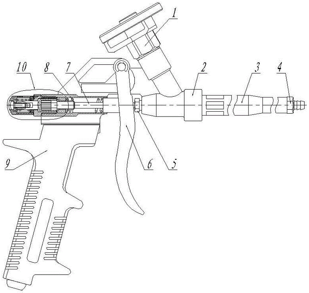
[0042] Such as figure 1Shown are two kinds of embodiments of the present invention, a kind of safety spray gun with adjustment reminding function, consists of gun nozzle 4, gun barrel 3, thimble 7, compression spring 8, gun body 2, opening adjustment device 10, trigger 6, Adapter 1 and handle 9 etc. are formed. The front of the gun body 2 is connected to the gun barrel 3, the front of the gun barrel 3 is connected to the gun nozzle 4, the rear and lower part of the gun body 2 is connected to the handle 9, the middle part of the gun body 2 is provided with a trigger 6, and a sealing device 5 is arranged between the gun body 2 and the trigger 6 , the front section of the thimble 7 is placed in the gun barrel 3, the trigger 6 is linked with the slider of the thimble 7; there is a hole at the front and upper part of the gun body 2, and the chemical agent with pressure enters the gun body 2 through the adapter 1 installed on the hole, The rear end of the gun body 2 is an opening a...

Embodiment 2

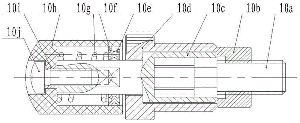
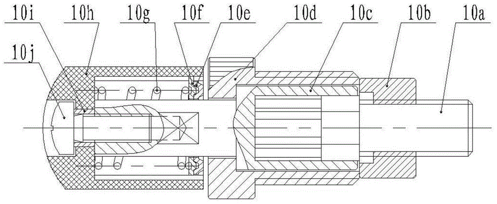
[0057] The difference between this embodiment and Embodiment 1 is that: the fixed part 10e and the rotating part 10f respectively include a circular base and protrusions evenly distributed on the ring, and dimples are formed between adjacent protrusions; the rotating part base and the adjustment The cap 10h is keyed, and the protrusion of the rotating part 10f is located in the recess of the fixed part, such as image 3 shown. The rest of the uniform structure is the same as Example 1.

[0058] When the adjustment rod 10c reaches the limit position, the adjustment rod 10c cannot rotate. If the external force continues to be applied at this time, the adjustment cap 10h will rotate relative to the adjustment rod 10c, and the protrusion of the rotation part 10f will break away from the current recess of the fixed part 10e. When the rotation part 10f When the protrusion enters the next recess of the fixing part 10e, the sounding component makes a sound, reminding the user that th...

Embodiment 3

[0060] The difference between this embodiment and Embodiment 1 is that the fixed part 10e and the rotating part 10f respectively include a circular base body and pits evenly distributed on the ring, the rotating part base is connected with the adjustment cap, and the fixed part The pits and the pits of the rotating part are aligned to form a marble accommodation chamber, and each marble accommodation chamber is provided with a marble 10k, such as Figure 4 shown. All the other structures are the same as in Example 1.

[0061] When the adjustment rod 10c reaches the limit position, the adjustment rod 10c cannot rotate. If the external force continues to be applied at this time, the adjustment cap 10h will rotate relative to the adjustment rod 10c, and the pit of the rotation part 10f will leave the marble 10k until the next position of the rotation part 10f. The pit cooperates with the marble 10k, and the sounding component sounds when the marble 10k enters the pit, reminding ...


PUM


Abstract

The invention discloses a foaming agent spray gun which comprises a gun nozzle, a gun barrel, a gun body, an adapter and a handle. A trigger is arranged on the gun body; an aperture adjusting device is connected to the rear end of the gun barrel and comprises a connecting base, a movable screw rod, a nut, an adjusting rod and a compressed spring; the connecting base comprises an end cover and a hollow connecting part; the movable screw rod and the adjusting rod are arranged in the connecting base; the adjusting rod is composed of a front section and a rear section; a shaft shoulder is formed at the place where the front section and the rear section are connected; a through hole is formed in the end cover of the connecting base; the movable screw rod comprises a screw rod section and a sliding section; a containing cavity is arranged in the front section of the adjusting rod; a limiting mechanism is arranged between the front section and the sliding section of the movable screw rod; the compressed spring is located between a thimble slide block and the nut and tightly compresses the nut on the connecting base; the adjusting rod rotates to enable the movable screw rod to move forwards or backwards along the axial direction. The foaming agent spray gun has the advantages of good safety and labor-saving aperture adjustment.

Description

technical field [0001] The invention belongs to the field of liquid injection, in particular to a polyurethane foam spray gun. Background technique [0002] Polyurethane foam has the functions of fixing, sound insulation, heat preservation, waterproof and plugging, so polyurethane foam is more and more widely used especially in the field of construction. [0003] Chinese patent ZL201020156717.2 discloses a spray gun for foam caulking agent, which includes a nozzle, a barrel, a gun body, an adapter and a handle. A hole is arranged on the gun body, and a chemical agent with pressure enters the gun body from the hole through the adapter. , the gun body is equipped with a trigger that can control the chemical agent entering the gun body to be ejected from the gun nozzle, and a retaining ring for one shaft is fixed at the connection between the trigger and the gun body through a pin shaft, and the rear end of the gun body is connected to the thimble opening device. The front par...

Claims


Application Information

Patent Timeline
Patent Type & Authority Applications(China)
IPC IPC(8): B05B11/02B05B15/00
CPCB05B11/0005B05B11/02
Inventor 沈卫东
Owner ZHEJIANG VOLCANO MACHINERY
Why Eureka
Try Eureka