
Electric screw driver with adjustable rotating speed

An electric screwdriver, speed technology, applied in the direction of transmission components, motor tools, transmission devices, etc., can solve the problems of inability to adjust the speed, complex structure, easy to produce impact, etc., achieve good torque conversion effect, compact structure, and easy to carry Effect

Inactive Publication Date: 2014-02-26
NORTHWESTERN POLYTECHNICAL UNIV
View PDF8 Cites 7 Cited by
  • Summary
  • Abstract
  • Description
  • Claims
  • Application Information

AI Technical Summary

Problems solved by technology

At present, there are two problems in electric screwdrivers that use gear sets for deceleration: first, in order to obtain an ideal transmission ratio, the gear reduction device is often complex in structure, and the torque conversion effect is poor; second, the gearbox can only provide a fixed transmission ratio. , that is, the electric screwdriver can only rotate at a constant speed and cannot be adjusted; when using a screwdriver in normal times, a large torque is only required when the screw is tightened or when the screw is just disassembled, and the torque required at other times is small
[0003] In the patent 201020232004, an electric screwdriver with a planetary gear set reduction transmission device is disclosed. It has two sets of planetary gear sets in series for deceleration. The structure is compact and small, and the torque conversion effect is good; however, the electric screwdriver cannot be adjusted.
In the patent 200720080072.7, a manual variable speed screwdriver is disclosed, which is composed of a handle and a variable speed gear connected by a screw, and the rotation speed of the screwdriver head can be adjusted during operation. The screwdriver has two adjustable speeds, one is normal speed, and the other is Accelerate the rotation, although the variable speed screwdriver can achieve speed regulation, but when shifting gears, a pair of gears will exit or enter meshing, this kind of transmission shifting is difficult and easy to produce impacts, in addition, the variable speed screwdriver realizes normal Switching between rotation and acceleration rotation does not meet the requirements for electric screwdriver deceleration

Method used


Image

  • Electric screw driver with adjustable rotating speed
  • Electric screw driver with adjustable rotating speed
  • Electric screw driver with adjustable rotating speed

Examples


Embodiment Construction

[0017] This embodiment is an electric screwdriver with adjustable rotational speed.

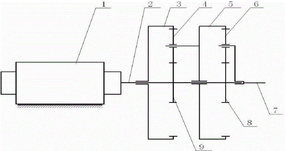
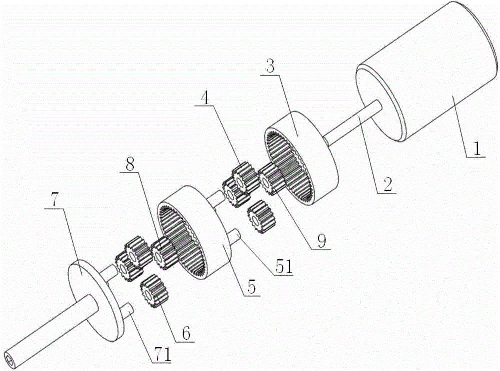
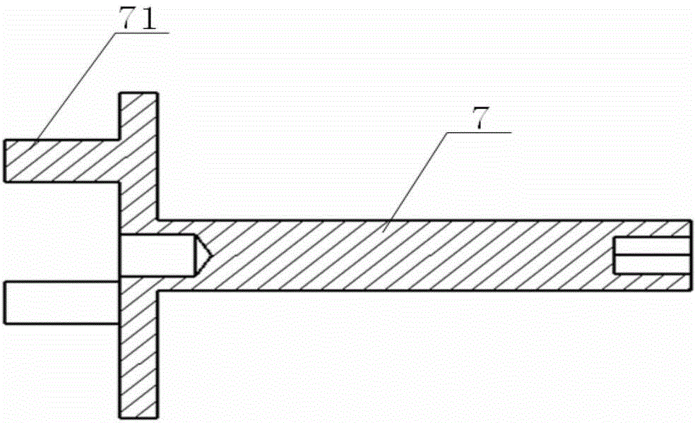
[0018] see figure 1 , figure 2 , image 3 , The electric screwdriver with adjustable speed of the present invention is composed of a motor, a combined gear train reducer, and a cutter rod drive shaft. The combined gear train reducer is fixed in the middle part of the electric screwdriver, the motor is located at the side end of the combined gear train reducer, and the knife rod drives The shaft is fixed on the other side end of the combined gear train reducer and is fixedly connected with the cutter bar. The combined gear train reducer is composed of a first-stage planetary gear train and a second-stage planetary gear train, including a first driving gear 9, a first sun gear 3, a first planetary gear 4, a second driving gear 8, a second sun gear 5, The first planetary gear shaft 51, the second planetary gear 6; the first sun gear 3 and the second sun gear 5 are both ring gears; the first ...


PUM


Abstract

The invention discloses an electric screw driver with an adjustable rotating speed. The electric screw driver is composed of a motor, a combined gear train decelerator and a cutter bar driving shaft, wherein the combined gear train decelerator is located in the middle of the electric screw driver; the motor is mounted behind the combined gear train decelerator; the cutter bar driving shaft is fixed in front of the combined gear train decelerator and is fixedly connected to a cutter bar; the cutter bar is changeable. When an output power of the motor is changeless, the combined gear train is utilized to change force at high rotating speed and low torque output by the motor into force at low rotating speed and great torque so as to be provided to the cutter bar; furthermore, a transmission ratio can be changed in the motor rotation process, gear can be shifted and speed can be changed at any time, and no rigid compact exists among gears during the gear shifting process. According to the practical need, other planetary reducers with fixed transmission ratio used for enlarging a speed change range can be mounted in series between the motor of the electric screw driver and the combined gear train decelerator.

Description

technical field [0001] The invention relates to a common electric tool, in particular to an electric screwdriver with adjustable rotational speed. Background technique [0002] Existing electric screwdrivers are usually driven directly by the motor to rotate the cutter head. Due to the high rotational speed and low torque of the motor drive shaft, the electric screwdriver head requires low rotational speed and high torque to tighten the screw. A gear set is added between the rotating components of the cutter head to convert the force output by the motor with high rotational speed and small torque into a force with low rotational speed and high torque to drive the rotating component of the cutter head. At present, there are two problems in electric screwdrivers that use gear sets for deceleration: first, in order to obtain an ideal transmission ratio, the gear reduction device is often complicated in structure and has poor torque conversion effect; second, the gearbox can onl...

Claims


Application Information

Patent Timeline
Patent Type & Authority Applications(China)
IPC IPC(8): B25B21/00F16H3/44F16H55/17
CPCB25B21/008F16H3/46F16H55/17F16H2200/2007
Inventor 田文龙宋保维张斌朱崎峰毛昭勇
Owner NORTHWESTERN POLYTECHNICAL UNIV
Learn More