Hydraulic substation oil circuit system

A technology of oil circuit system and hydraulic substation, which is applied in the direction of fluid pressure actuation system components, fluid pressure actuation devices, mechanical equipment, etc., and can solve problems such as cumbersomeness, potential safety hazards, and damage to hydraulic actuators

Active Publication Date: 2014-02-26
无锡市海航电液伺服系统股份有限公司
View PDF11 Cites 5 Cited by
  • Summary
  • Abstract
  • Description
  • Claims
  • Application Information

AI Technical Summary

Problems solved by technology

[0003] The hydraulic substations in the prior art usually use pressure reducing valves to realize the adjustment of different oil pressures. Although the hydraulic substations with this structure are simple in structure and easy to produce, they also have some functional defects. During the initial debugging of the components, the oil pressure needs to work at a low pressure state, and the oil pressure needs to be at a high pressure state during normal operation. The simple pressure reducing valve adjustment is undoubtedly clumsy and cumbersome. During the pressure process, the sudden pressure increase and decrease will reduce the service life of the hydraulic actuators, and sometimes cause damage to the hydraulic actuators. At the same time, there are serious safety hazards.

Method used


Image

  • Hydraulic substation oil circuit system

Examples


Embodiment Construction

[0012] The present invention will be described in further detail below according to the drawings and embodiments.

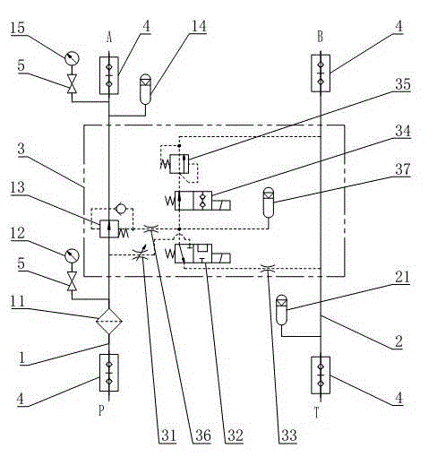
[0013] Such as figure 1 As shown, a hydraulic substation oil circuit system described in the embodiment of the present invention includes a main oil circuit 1 and an oil return circuit 2, the main oil circuit 1 has a main oil inlet P and a working oil inlet A, and the oil return The oil circuit 2 has a working oil outlet B and a main oil return port T, and the main oil circuit 1 is equipped with a high-pressure oil filter 11, a system pressure gauge 12, and a pressure reducing valve main valve in sequence from the independent oil inlet P to the working oil inlet A 13. The high-pressure accumulator 14 and the secondary pressure gauge 15; the main oil circuit 1 diverges from the system pressure gauge 12 and the main valve 13 of the pressure reducing valve, and is connected with a throttle valve 31, and the throttle valve 31 is connected in series with an electromag...


PUM


Abstract

The invention relates to a hydraulic substation oil circuit system which comprises a main oil circuit and a return oil circuit. The main oil circuit is provided with a main oil inlet and a working oil inlet, the return oil circuit is provided with a working oil outlet and a main return opening, a control oil circuit is arranged between the main oil circuit and the return oil circuit and comprises a main pressure reducing valve arranged on the main oil circuit, the main oil circuit is split between the main pressure reducing valve and the main oil inlet and connected with a throttling valve, the throttling valve is serially connected with an electromagnetic directional valve, the electromagnetic directional valve returns into the return oil circuit through a first throttling hole and is serially connected with an electromagnetic ball valve, the electromagnetic ball valve is serially connected with an overflow valve, the overflow valve returns into the return oil circuit, the main pressure reducing valve is communicated with an energy accumulator through a second throttling hole, and the energy accumulator, the second throttling hole, the electromagnetic directional valve and the electromagnetic ball valve are mutually communicated in an intersected manner. According to the hydraulic substation oil circuit system with the structure, the rate of the pressure lifting and pressure reducing process can be adjusted, the service life of a hydraulic actuator is prolonged, and potential safety hazards are eliminated.

Description

technical field [0001] The invention relates to an oil circuit system of a hydraulic substation, belonging to the technical field of hydraulic station control. Background technique [0002] In the hydraulic system, in addition to the oil source, hydraulic actuators and pipelines, there is also an intermediate device for processing large oil sources and simultaneously supplying multiple hydraulic actuators with different oil pressures, which is the hydraulic substation. [0003] The hydraulic substations in the prior art usually use pressure reducing valves to realize the adjustment of different oil pressures. Although the hydraulic substations with this structure are simple in structure and easy to produce, they also have some functional defects. During the initial debugging of the components, the oil pressure needs to work at a low pressure state, and the oil pressure needs to be at a high pressure state during normal operation. The simple pressure reducing valve adjustment...

Claims


Application Information

Patent Timeline
Patent Type & Authority Applications(China)
IPC IPC(8): F15B1/02F15B21/00
Inventor 朱晓兵刘红霞
Owner 无锡市海航电液伺服系统股份有限公司
Why Eureka
Try Eureka