Automatic pressure maintaining device

A pressure-maintaining device, an automatic technology, applied in the direction of fluid pressure actuating device, servo motor assembly, mechanical equipment, etc., can solve the problem of unfavorable pressure-maintaining device, and achieve the effect of good long-term pressure-maintaining effect

Active Publication Date: 2014-02-26
CHANGDE ZHONGLIAN ZHONGKE HYDRAULIC +1
View PDF6 Cites 11 Cited by
  • Summary
  • Abstract
  • Description
  • Claims
  • Application Information

AI Technical Summary

Problems solved by technology

However, since the pressure holding device needs to be used in the case of continuous operation of construction machinery, the pressure oil source is higher than the set pressure holding value of the pressure holding device for a long time at this time
Although in theory the pressure holding device can cut off the connection with the pressurized oil source, in fact, due to the hydraulic characteristics of the hydraulic components in the pressure holding device, the pressure holding chamber in the pressure holding device and the pressurized oil will not work continuously for a long time. It is inevitable that there will be internal leakage between the sources, which will cause the pressure holding device to be continuously pressurized, making its pressure value significantly higher than the set pressure holding value, which is very unfavorable to the actuator using the pressure holding device

Method used


Image

  • Automatic pressure maintaining device
  • Automatic pressure maintaining device
  • Automatic pressure maintaining device

Examples


Embodiment Construction

[0042] Specific embodiments of the present invention will be described in detail below in conjunction with the accompanying drawings. It should be understood that the specific embodiments described here are only used to illustrate and explain the present invention, and are not intended to limit the present invention.

[0043] In the invention, unless otherwise specified, the used orientation words such as "left and right" are usually the directions of the left and right sides with respect to the width direction of the paper.

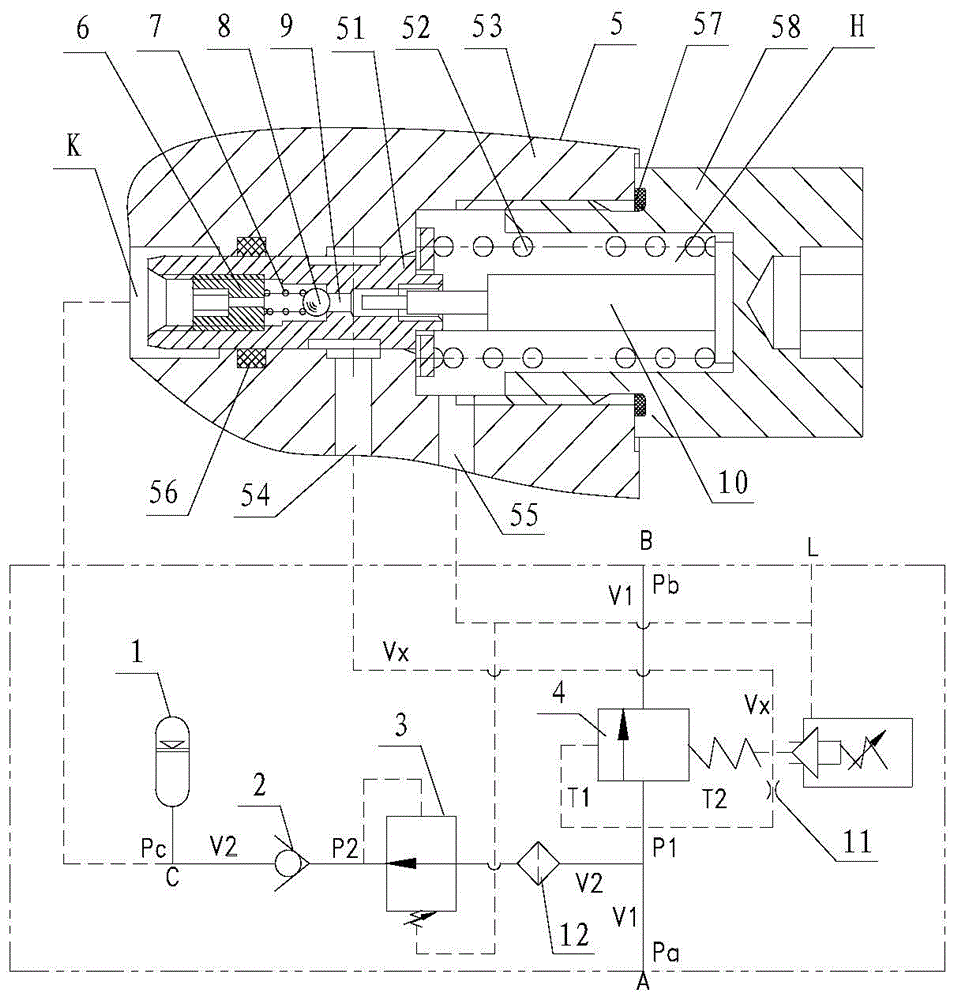
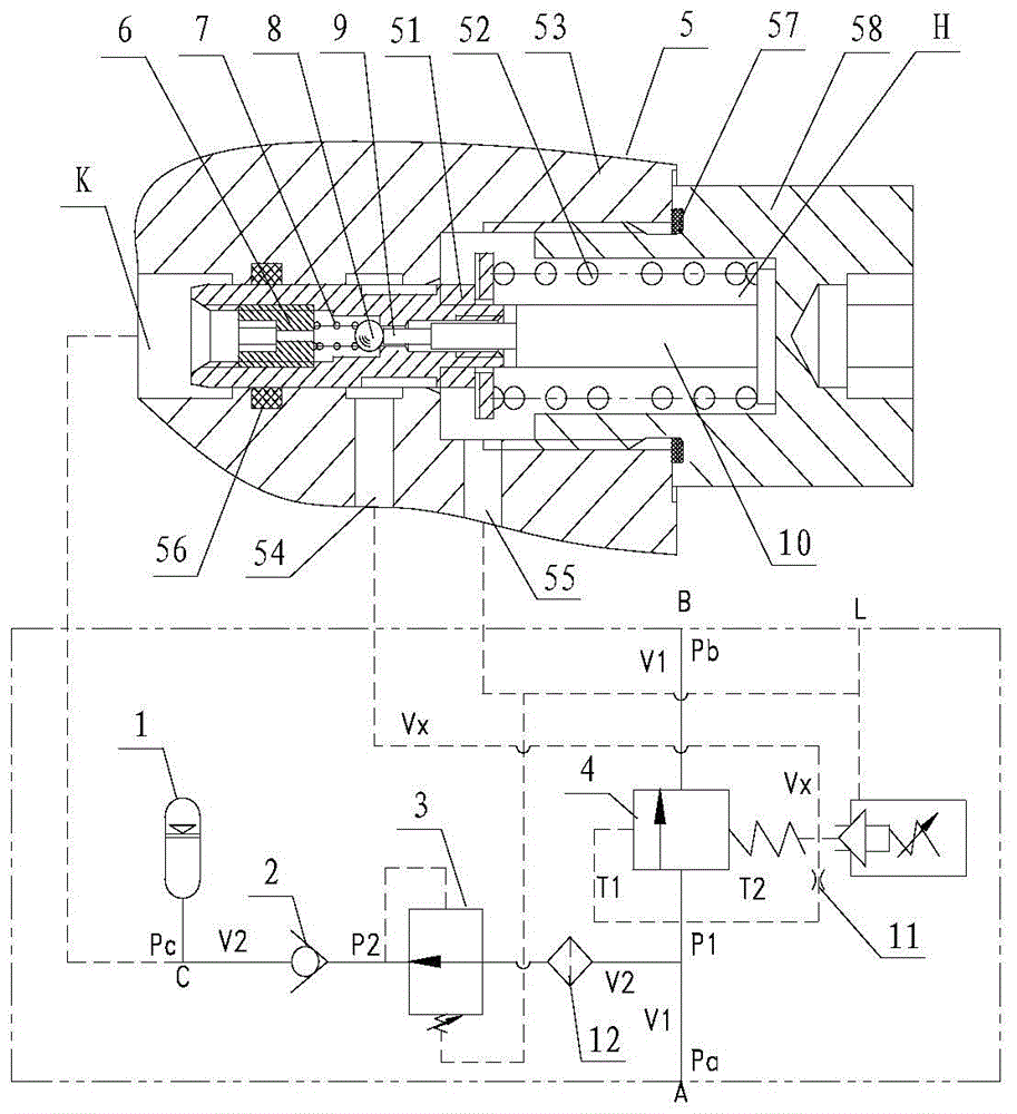
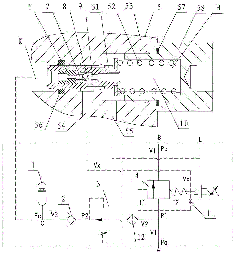
[0044] figure 1 It is a schematic diagram of the hydraulic structure of the automatic pressure maintaining device according to a preferred embodiment of the present invention. figure 1 It can be seen that the device has an oil inlet A, an oil outlet B, a pressure-holding oil port C and an oil return port L, and an internal main oil circuit V1 is connected between the oil inlet A and the oil outlet B, and the oil inlet A A pressure oil circuit V2 is con...


PUM


Abstract

The invention discloses an automatic pressure maintaining device which is provided with an oil inlet (A), an oil outlet (B), a pressure-maintaining oil port (C) and an oil return port (L). The automatic pressure maintaining device comprises an energy accumulator (1), a pressure-maintaining one-way valve (2), a pressure reducing valve (3), a sequence valve (4) and a pressure-maintaining control valve (5), the sequence valve is arranged on an internal main oil way (V1), the pressure reducing valve is arranged in a pressurizing oil way (V2), the pressure-maintaining one-way valve (2) is arranged between the energy accumulator and the pressure reducing valve, a reversing port of the pressure-maintaining one-way valve (2) is hydraulically connected with the energy accumulator, set opening pressure (P1) of the sequence valve is larger than set working pressure (P2) of the pressure reducing valve, and the pressure-maintaining control valve is arranged on a connecting oil way between the energy accumulator and the oil return port, so that when a hydraulic pressure value in the energy accumulator is larger than a pressure-maintaining lower limit value (Px), the sequence valve is controlled to be opened, and when the hydraulic pressure value is larger than a pressure-maintaining upper limit value (Ps), the energy accumulator is controlled to return oil to the oil return port and depressurize. The automatic pressure maintaining device can realize automatic pressurizing, pressure maintaining and depressurizing, and has good long-time pressure maintaining effect.

Description

technical field [0001] The invention relates to a pressure maintaining device, in particular to a pressure maintaining device with automatic pressure charging and pressure releasing functions suitable for hydraulic automatic control systems of engineering machinery. Background technique [0002] In the hydraulic system of construction machinery, some actuators (such as the power assist system of the steering wheel) need an additional pressure-stabilizing device to work properly. When the actuator is working, the pressure holding device can automatically charge the pressure to the set value, and when the actuator stops working, the pressure holding device can play a good pressure holding effect. However, since the pressure-holding device needs to be used in the case of continuous operation of construction machinery, the pressurized oil source is higher than the set pressure-holding value of the pressure-holding device for a long time. Although in theory the pressure holding ...

Claims


Application Information

Patent Timeline
Patent Type & Authority Applications(China)
IPC IPC(8): F15B1/02F15B13/02
Inventor 向治平艾志浩潘文华
Owner CHANGDE ZHONGLIAN ZHONGKE HYDRAULIC
Why Eureka
Try Eureka