Auxiliary bridge appearance detection device

A technology for auxiliary detection and appearance, which is used in measurement devices, camera devices, surveying and mapping and navigation, etc. It can solve the problems of high cost of inspection vehicles, inability of C-shaped brackets to achieve multi-angle and comprehensive inspection, and complex inspection processes. The operation skills are not high, suitable for large-scale promotion and development, and the equipment is easy to operate.

Inactive Publication Date: 2014-02-26
JSTI GRP CO LTD
View PDF6 Cites 7 Cited by
  • Summary
  • Abstract
  • Description
  • Claims
  • Application Information

AI Technical Summary

Problems solved by technology

[0004] 1. The cost of inspection vehicles is relatively expensive. At present, there are very few units equipped with special bridge inspection vehicles, and there are fewer units on the market that can provide corresponding rental conditions, which restricts its development.
[0005] 2. The detection efficiency of the detection vehicle is low. In the actual operation process, the detection vehicle needs to be continuously moved to reach the corresponding part for detection. The detection process is more complicated and the efficiency is relatively low.
[0006] 3. Affect traffic. For bridges and pavements that are in operation, because the inspection vehicles are generally large trucks, they need to occupy 1.5 to 2 lanes during the inspection process, which affects the smooth flow of traffic and is inconvenient to use
However, the whole device needs to redesign the car body and related supporting facilities by itself, which requires a large investment and a relatively long production cycle.
[0008] Chinese patent (CN 202298459 U) discloses a bridge detection device, including a C-shaped bracket, the bracket is retractable, and the two ends of the bracket are respectively equipped with an eyepiece and a detection mirror, and the image detected by the detection mirror is transmitted through a light-guiding optical fiber. For the eyepiece, although it solves the problem of knowing the site conditions without the actual inspection by technicians, the C-shaped bracket cannot realize multi-angle comprehensive inspection, which limits its scope of use
[0009] Moreover, in the process of bridge detection, underwater detection is also the focus of the detection work. At present, there is no instrument specifically for the detection of underwater parts of bridges, and there is no practical detection method. Most of them rely on divers to dive underwater and approach the surface of the structure for observation. , low efficiency, high cost

Method used


Image

  • Auxiliary bridge appearance detection device
  • Auxiliary bridge appearance detection device

Examples


Embodiment 1

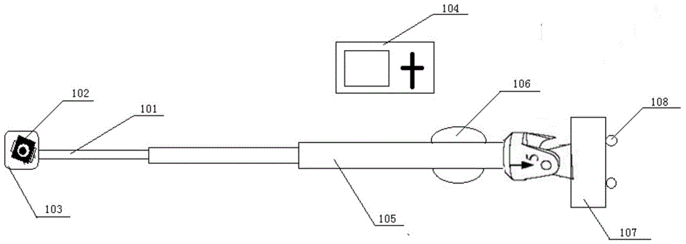
[0029] Such as figure 1 The shown bridge appearance auxiliary detection device of the present invention includes three telescopic probe rods, and the diameter of each telescopic probe rod decreases successively, wherein the telescopic probe rod with the smallest diameter is the first telescopic probe rod 101, and the top is movably connected with a camera 102 at 360 degrees. , wherein the outside of the camera 102 is wrapped by a sealed fully transparent waterproof cover 103, and the inside of the camera 102 has a wireless signal transmitter. The auxiliary bridge appearance detection device also includes a remote control device 104 with a display screen as a receiving mechanism for receiving video or photo information transmitted by the camera 102, wherein the remote control device 104 has a wireless signal receiver inside.

[0030] In order to improve the operating comfort of the testing personnel, the section with the largest diameter of the telescopic probe rod is the third...

Embodiment 2

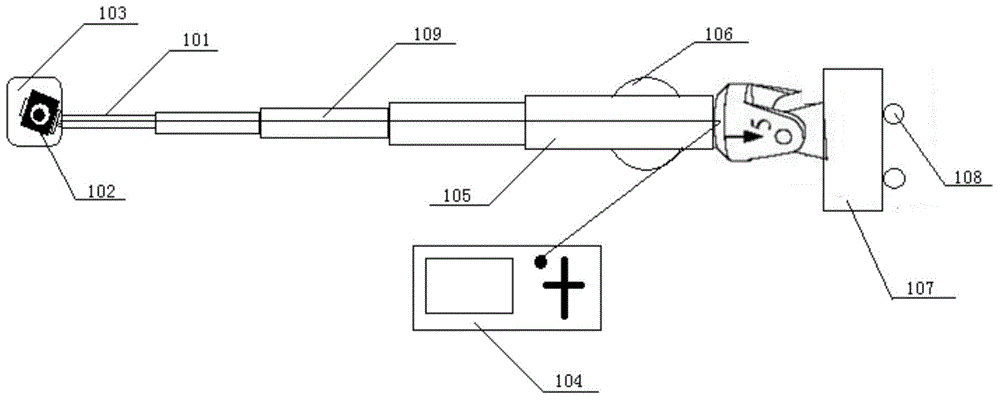
[0033] Such as figure 2 The shown bridge appearance auxiliary detection device of the present invention includes five telescopic probe rods, the telescopic probe rods are hollow structures, and the diameter of each telescopic probe rod decreases successively, wherein the telescopic probe rod with the smallest diameter is the first telescopic probe rod 101, The diameter of the first telescopic probe rod 101 is greater than the diameter of the transmission line 109, and a camera 102 is movably connected to the top of the first telescopic probe rod 101 at 360 degrees, wherein the outside of the camera 102 is wrapped by a sealed fully transparent waterproof cover 103, and the inside of the camera 102 has signal transmitter. The auxiliary bridge appearance detection device also includes a remote control device 104 with a display screen as a receiving mechanism for receiving video or photo information transmitted by the camera 102, wherein the remote control device 104 has a signal...


PUM


Abstract

The invention discloses an auxiliary bridge appearance detection device which comprises a sectionalized telescopic detection rod, wherein the diameters of all sections of the sectionalized telescopic detection rod are reduced sequentially; a photographing mechanism is arranged on the top of the section with the minimum diameter of the detection rod; a waterproof cover is arranged outside the photographing mechanism; a wireless signal emitter is arranged in the photographing mechanism. The auxiliary bridge appearance detection device also comprises a receiving mechanism which is remote control equipment with a display screen; a wireless signal receiver is arranged in the remote control equipment. The photographing equipment is arranged at the front end of the telescopic detection rod and has a waterproofing function, so that a photographing detection function under water is realized; a photographed on-site working condition is transmitted to the receiving equipment through a wired or wireless signal, so that a user can learn about the use condition of a bridge in real time; furthermore, the whole equipment is low in manufacturing cost and suitable for large-scale popularization and development; meanwhile, the equipment is easy to operate and has low requirements on the equipment operation skills of on-site detection operators, and thus the development of the detection work is facilitated.

Description

technical field [0001] The invention relates to a civil bridge detection device, in particular to an auxiliary device for bridge appearance detection. Background technique [0002] Bridges are buildings erected on rivers, lakes and seas to allow the smooth passage of vehicles and pedestrians. A bridge generally consists of a superstructure, a substructure and ancillary structures. The superstructure mainly refers to the bridge span structure and support system; the substructure includes abutments, piers and foundations; , diversion engineering, etc. Bridges enable roads, railroads, or walkways to span rivers, lakes, valleys, canyons, or other roads. Bridges are mostly fixed, but some bridges can be raised or rotated. Regardless of the type of bridge, the design and construction problem facing engineers is to make the bridge structure strong so that it will not sag or crack under the weight. [0003] With the increase of the service life, the inspection period for the app...

Claims


Application Information

Patent Timeline
Patent Type & Authority Applications(China)
IPC IPC(8): G01C11/00
CPCG01C11/02
Inventor 朱晓文傅斌赖广胜王敏张行
Owner JSTI GRP CO LTD
Why Eureka
Try Eureka