Device for arranging monitoring points of tunnel and operating method thereof

A technology for tunnel monitoring and monitoring points, applied in active optical measuring devices, measuring point marks, plumb lines, etc., can solve problems affecting the authenticity of measurement data, complicated operation, and poor practicability, and realize three-dimensional continuous layout , improve the accuracy, the effect of simple structure

Active Publication Date: 2014-02-26
SHANDONG UNIV
View PDF3 Cites 7 Cited by
  • Summary
  • Abstract
  • Description
  • Claims
  • Application Information

AI Technical Summary

Problems solved by technology

[0003] Vault subsidence and peripheral displacement are mandatory items for monitoring and measurement. The method is to bury three measuring points on a cross-section and use them to obtain corresponding data by extensometer measurement. However, in the current measurement method, the number of measuring points The accuracy of the embedding method is not high, it is difficult to ensure that the three measuring points are on the same section, and it is difficult to ensure that the section is perpendicular to the tunnel axis, which affects the authenticity of the measurement data
[0004] Invention patent (application number: 201110226

Method used


Image

  • Device for arranging monitoring points of tunnel and operating method thereof
  • Device for arranging monitoring points of tunnel and operating method thereof
  • Device for arranging monitoring points of tunnel and operating method thereof

Examples


Embodiment Construction

[0034] The present invention will be further described below in conjunction with the accompanying drawings and embodiments.

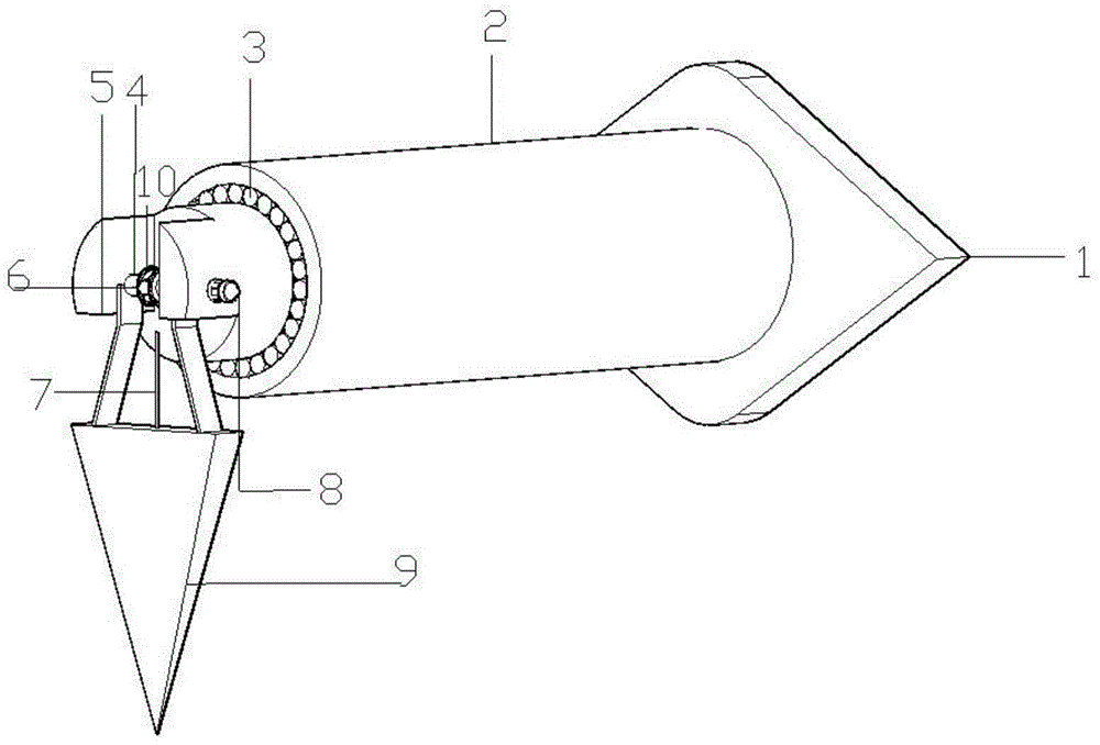
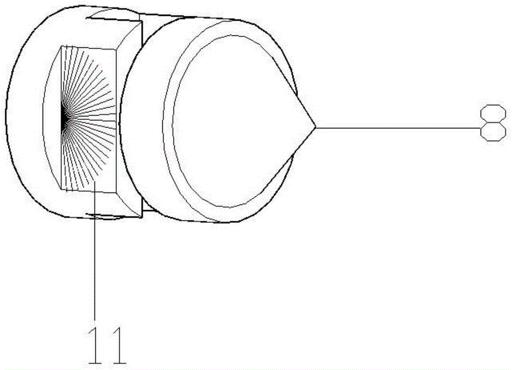
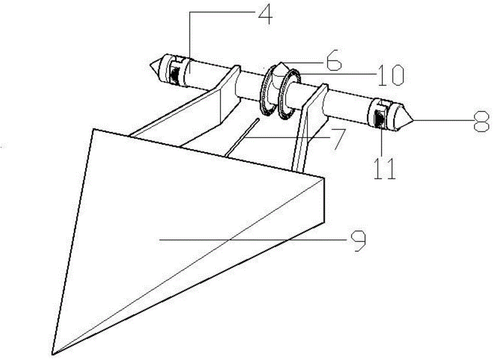
[0035] Such as figure 1 , figure 2 , image 3 As shown, a device for laying tunnel monitoring points, including a base 1, a pillar 2, a rotating shaft 5, a column pulley 3, a weight 9, a beam 4, a dial and a laser emitter, wherein the laser emitter includes a section positioning Laser emitter 8, monitoring point positioning laser emitter 6; the dial includes a monitoring point positioning dial 10 and a section positioning dial 11, the pillar 2 is fixed at the center of the base 1, and the rotating shaft 5 is nested and connected to the pillar 2 through the cylindrical pulley 3 At the top, the crossbeam 4 runs through the rotating shaft 5, the monitoring point positioning laser emitter 6 is fixed on the center of the crossbeam 4, the section positioning laser emitter 8 is connected to both ends of the crossbeam 4; the monitoring point positioning dial...


PUM


Abstract

The invention discloses a device for arranging monitoring points of a tunnel. The device comprises a base, a supporting column, a rotary shaft, columnar pulleys, a counter weight, a cross beam, dials and laser transmitters, wherein the laser transmitters comprise two section positioning laser transmitters and a monitoring point positioning laser transmitter; the dials comprise two monitoring point positioning dials and two section positioning dials; the supporting column is fixedly arranged in the center of the base, the rotary shaft is sleeved and connected to the top end of the supporting column through the columnar pulleys, the cross beam penetrates through the rotary shaft, the monitoring point positioning laser transmitter is fixedly arranged in the center of the cross beam, and the section positioning laser transmitters are connected to two ends of the cross beam; the monitoring point positioning dials are fixedly arranged on two sides of the monitoring point positioning laser transmitter respectively, and the section positioning dials are fixedly arranged inside the section positioning laser transmitters. The device disclosed by the invention guarantees that three monitoring points are located on a same monitoring section and the monitoring section is vertical to the tunnel in axis direction, so that the precision of monitoring results is improved. The monitoring sections at different intervals in position can be realized, so that the monitoring sections are convenient to arrange.

Description

technical field [0001] The invention relates to a device for laying tunnel monitoring points and an operation method thereof. Background technique [0002] With the deepening of the understanding of the mechanical characteristics and complexity of underground engineering, since the 1950s, the world has begun to monitor the stability of surrounding rock and support through on-site measurement of underground engineering, and apply on-site The measurement results correct the design and guide the construction. The principle of on-site measurement is mainly to conduct numerical analysis and theoretical analysis based on the data obtained from on-site measurement, and make a judgment closer to the engineering century, so as to correct support parameters and guide construction. [0003] Vault subsidence and peripheral displacement are mandatory items for monitoring and measurement. The method is to bury three measuring points on a cross-section and use them to obtain corresponding...

Claims


Application Information

Patent Timeline
IPC IPC(8): G01C15/02
CPCG01C15/002G01C15/02G01C15/10
Inventor 李术才刘洪亮李利平石少帅周宗青王旌胡聪
Owner SHANDONG UNIV
Why Eureka
Try Eureka